
Gestor de datos universal RSG35: Guía de conexión eléctrica y operación
El gestor de datos universal RSG35 se utiliza ampliamente en el campo de la automatización industrial. Su correcta conexión eléctrica y operación normalizada son clave para garantizar el funcionamiento estable del equipo. Basado en la documentación técnica oficial, este artículo organiza sistemáticamente los requisitos de cableado, la asignación de terminales, la tensión de alimentación, los relés, las entradas digitales, las entradas analógicas y el método de operación del panel frontal del RSG35, para referencia del personal técnico de ingeniería y de compras.
1. Conexión eléctrica
1.1 Requisitos de cableado
Para garantizar la seguridad del equipo y del personal, la conexión eléctrica del RSG35 debe cumplir estrictamente las siguientes normas:
- Todas las conexiones del equipo deben realizarse con la alimentación desconectada.
- Está prohibido conectar líneas de tensión muy baja de seguridad y líneas de tensión peligrosa juntas al relé.
- Además de las líneas del relé y de la tensión de alimentación, solo se pueden conectar circuitos de energía limitada conformes con la norma EC/EN 61010-1.
- Antes de realizar otras conexiones eléctricas, se debe establecer la conexión a tierra.
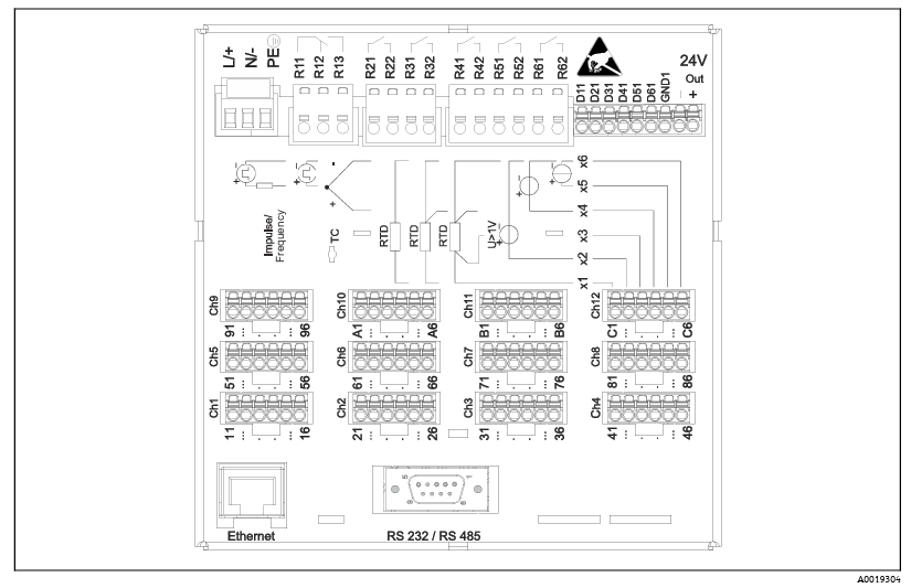
1.2 Diagrama de asignación de terminales de cableado en la parte posterior del equipo
La asignación de terminales de cableado en la parte posterior del equipo se muestra en la siguiente figura. Conecte cada línea correctamente según el diagrama.
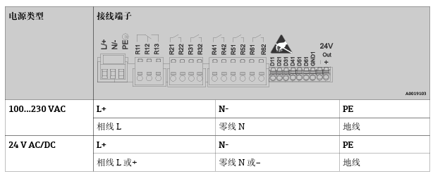
1.3 Tensión de alimentación del instrumento RSG35
El modo de conexión de la tensión de alimentación del RSG35 se muestra en la siguiente figura. Asegúrese de que la tensión de alimentación esté dentro del rango especificado para el equipo.
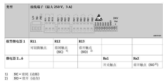
1.4 Relés
La asignación de terminales de cableado de los relés se muestra en la siguiente figura. Tenga en cuenta los requisitos de seguridad para la conexión de los relés.
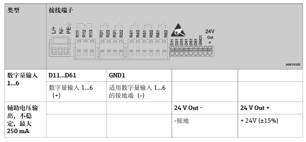
1.5 Entradas digitales; salida de tensión auxiliar
El modo de conexión de las entradas digitales y la salida de tensión auxiliar se muestra en la siguiente figura.
1.6 Entradas analógicas
El modo de conexión de las entradas analógicas se muestra en la siguiente figura. Conecte correctamente según el tipo de señal.

2. Método de operación
2.1 Diagrama del panel frontal del equipo con la tapa abierta
La disposición del panel frontal del equipo se muestra en la siguiente figura. La función de cada componente se describe a continuación.
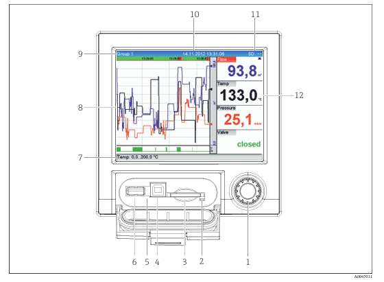
2.2 Descripción de las funciones de los componentes del panel frontal
A continuación se presentan los componentes del panel frontal y las instrucciones de operación:
- Mando giratorio (jog dial): se utiliza para avance rápido/retroceso lento y para operaciones de pulsación/mantener.
- En modo de visualización: girar el mando permite cambiar entre diferentes grupos de señales; pulsar el mando muestra el menú principal.
- En modo de configuración o en menús de selección: girar en sentido antihorario mueve hacia arriba o hacia la izquierda el elemento o el cursor, y cambia parámetros; girar en sentido horario mueve hacia abajo o hacia la derecha el elemento o el cursor, y cambia parámetros.
- Pulsación rápida (< 2 s): selecciona el parámetro de función resaltado y confirma el cambio de parámetro (tecla Intro).
- Ver ayuda en línea: mantener pulsado el mando giratorio (> 3 s) para mostrar información sobre el parámetro de función seleccionado. Mantener pulsado el botón "Atrás" del mando giratorio (> 3 s) para salir inmediatamente del menú y cambiar el equipo al modo de visualización.
- Indicador LED en la ranura para tarjeta SD: el LED naranja se enciende cuando el equipo lee o escribe en la tarjeta SD. ¡No extraiga la tarjeta SD mientras el LED esté encendido! ¡De lo contrario, existe riesgo de pérdida de datos!
- Ranura para tarjeta SD: para insertar la tarjeta SD.
- USB B "ranura esclava": por ejemplo, para conectar a un ordenador personal o portátil.
- Indicador LED verde: encendido indica que hay tensión.
- USB A "ranura maestra": por ejemplo, para conectar una memoria USB o un teclado externo.
- Modo de visualización: muestra alternativamente el estado de las entradas analógicas o digitales con el color de canal correspondiente (por ejemplo, configuración del rango de escala). En modo de configuración: puede mostrar diferentes informaciones según el tipo de visualización.
- Modo de visualización: muestra la ventana de valores medidos (por ejemplo, visualización de curvas). En modo de configuración: muestra el menú de operación.
- Modo de visualización: nombre del grupo actual, tipo de análisis. Modo de configuración: nombre del elemento de operación actual (título del diálogo).
- Modo de visualización: muestra la fecha/hora actual.
- Modo de visualización: muestra alternativamente el porcentaje de espacio utilizado de la tarjeta SD o de la memoria USB. Al mismo tiempo, muestra alternativamente iconos de estado e información de almacenamiento (consulte la tabla siguiente). En modo de configuración: muestra la contraseña de operación de "acceso directo" actual.
- Modo de visualización: muestra el valor medido actual y el estado de fallo/alarma.
2.3 Iconos de estado e información de almacenamiento
La siguiente tabla enumera los iconos de estado que pueden aparecer en el modo de visualización y su significado:
| Icono de estado | Significado |
|---|---|
| (ejemplo de icono) | Tarjeta SD insertada y funcionando correctamente |
| (ejemplo de icono) | Memoria USB conectada |
| (ejemplo de icono) | Almacenamiento de datos en curso |
| (ejemplo de icono) | Fallo o alarma |
Nota: consulte la pantalla del equipo o el manual completo para los iconos específicos.