
1. General Installation Requirements
The installation quality of the Promass 40/80/83 series mass flowmeters directly affects measurement accuracy and long-term stability. Correct installation can prevent measuring tube deformation, bubble accumulation, and cavitation, ensuring the sensor operates properly.
Before installation, confirm that the pipeline is well aligned, the flanges are aligned without offset, and support measures are taken to prevent vibration interference. The key installation points are described below.
2. Pipe Stress and Support
2.1 Pipe Alignment and Flange Alignment
Before installation, check and confirm whether the centers of the pipes before and after the flowmeter are directly aligned, that is, on the same horizontal line without offset in other directions.
Also check whether the flanges welded on the pipes before and after are properly aligned. The flanges and flange holes must not be offset; otherwise, additional stress will be generated, causing deformation of the measuring tube and measurement errors.
2.2 Pipe Support and Vibration Prevention
Good support is recommended for the pipes before and after the flowmeter to prevent pipeline vibration from affecting measurement. To protect the pipeline, appropriate brackets should be used when the sensor is too heavy.
- Confirm that the centers of the pipes before and after are aligned without offset
- Check flange and flange hole alignment
- Provide support for the pipes before and after to reduce vibration
- Add brackets when the sensor is too heavy
3. Avoiding Bubbles and Cavitation
3.1 Effect of Bubbles on Measurement
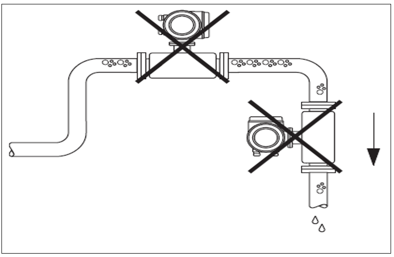
When bubbles are entrained in the measuring tube, measurement errors will occur. The following installation positions should be avoided:
- Installation at the highest point of the pipeline, which causes air accumulation
- Direct installation at the outlet of a downward vent pipe
3.2 Ideal Installation Method
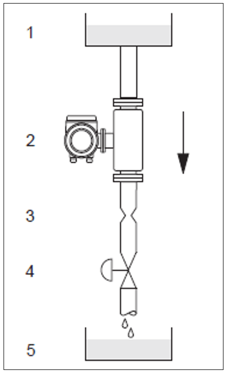
The ideal installation method for the flowmeter is to install it on a vertical pipe with the fluid flowing upward through the flowmeter. When the flowmeter is installed on a downward pipe (such as in batching control) and the fluid flows downward, the correct installation method is as shown in the figure: install a restriction orifice plate smaller than the nominal diameter of the pipe in the flowmeter pipeline to prevent the measuring tube from being emptied.
In the figure: 1 = supply tank 2 = sensor 3 = restriction orifice plate 4 = valve 5 = batching storage tank
3.3 System Pressure and Cavitation Prevention
It is important to ensure that cavitation does not occur, because cavitation affects the vibration of the measuring tube. Under normal conditions, no special measures are required when measuring fluids with properties similar to water.
For liquids with low boiling points (hydrocarbons, solvents, liquefied gases) or in suction pipelines, the system should have sufficiently high pressure to ensure that the pressure is not lower than the vapor pressure, that is, the liquid will not boil and will not vaporize.
Therefore, the optimal installation position for the sensor is: downstream of the pump (to avoid vacuum) and at the lowest point of a vertical pipe.
4. Installation Orientation and Transmitter Direction
4.1 Flow Direction Confirmation
Confirm that the arrow direction on the sensor nameplate matches the fluid flow direction. For vertical installation, it is recommended to have the fluid flow upward (View V), which allows entrained solid particles to settle, gas to rise through the measuring tube, and all fluid in the measuring tube to be drained, avoiding solid deposition.
4.2 Horizontal Installation Requirements
For horizontal installation, the measuring tube must be installed horizontally. The correct installation is with the transmitter housing vertically upward or downward (View H1/H2). The transmitter housing should be avoided being on the same horizontal plane as the pipeline.
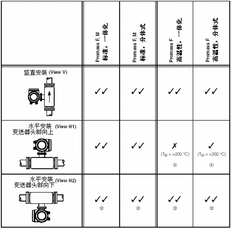
Where: √√ = recommended installation position, √× = recommended in certain cases, × = not allowed installation position.
4.3 Ambient Temperature Considerations
To ensure that the transmitter installation ambient temperature is within the range of -20°C to 60°C, the following installation positions are recommended:
- High-temperature fluid (>200°C): Use horizontal installation with the transmitter head downward (View H2) or vertical installation (View V)
- Low-temperature fluid: Use horizontal installation with the transmitter head upward (View H1) or vertical installation (View V)
4.4 Special Installation Instructions
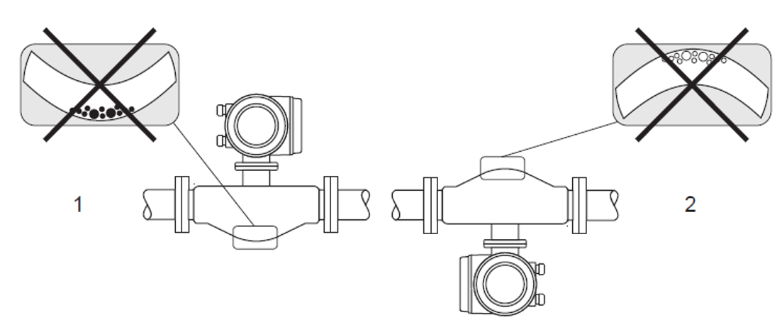
The measuring tubes of Promass F/E/H are all slightly bent tubes. For fluids with solid particles and gas overflow, the installation diagram is as follows. Therefore, the characteristics of the fluid must be considered during horizontal installation.
5. Upstream and Downstream Straight Pipe Section Requirements
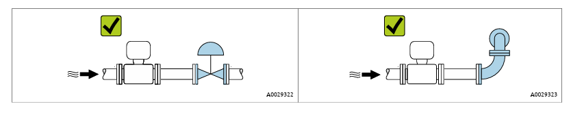
On the premise of ensuring that cavitation does not occur, no additional preventive measures are required to avoid disturbances caused by pipe fittings (such as valves, elbows, or tees) that interfere with measurement. The installation method diagram is as follows.
6. Summary of Installation Points
| Item | Requirement |
|---|---|
| Pipe alignment | Centers of pipes before and after aligned, flanges without offset |
| Support and vibration prevention | Support pipes before and after, add brackets when sensor is too heavy |
| Bubble avoidance | Avoid highest point and vent pipe outlet |
| Ideal installation | Vertical pipe, fluid flowing upward |
| System pressure | Not lower than vapor pressure, prevent cavitation |
| Transmitter direction | For horizontal installation, housing vertically upward or downward |
| Ambient temperature | -20°C to 60°C, choose corresponding orientation for high/low temperature |
| Straight pipe section | No additional measures required when there is no cavitation |
Following the above installation specifications can ensure long-term stable operation of the Promass 40/80/83 flowmeter and obtain accurate measurement results.