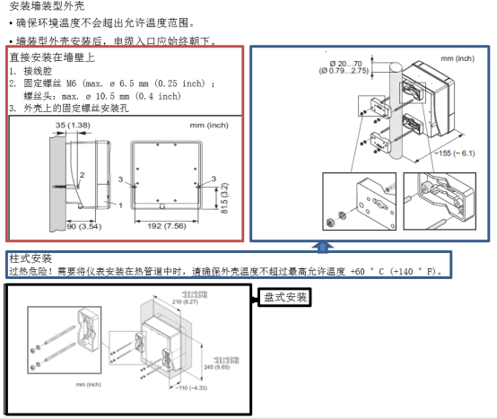
Guía de instalación del caudalímetro másico térmico T-mass 65
Que la tubería esté llena es un requisito previo para una medición precisa con caudalímetros térmicos. Por lo tanto, al instalar el caudalímetro, asegúrese de cumplir con los siguientes requisitos.
I. Ubicación de instalación
Las perturbaciones del estado del fluido tienen un impacto enorme en los instrumentos que miden según el principio de difusión térmica. Una ubicación de instalación correcta es la base para garantizar la precisión de medición.
- Cumpla con los requisitos recomendados de longitud de tramos rectos aguas arriba y aguas abajo.
- Una amplia experiencia práctica en ingeniería es un requisito previo para el diseño e instalación correctos del sistema de tuberías.
- Asegúrese de la orientación y ubicación de instalación correctas del sensor.
- Tome las medidas necesarias para reducir o evitar la condensación (por ejemplo: instalar separadores de condensado, realizar aislamiento térmico, etc.).
- Se deben cumplir los requisitos de temperatura ambiente máxima permitida y rango de temperatura del medio.
- Instale el transmisor en un lugar sombreado o instale una cubierta protectora.
- Por consideraciones de estructura mecánica, para proteger la tubería, al instalar sensores de gran peso se recomienda usar una base de montaje.
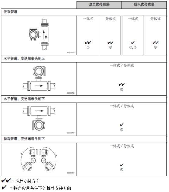
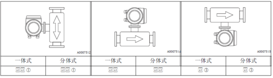
① Al medir gases saturados o gases impuros, se recomienda una orientación de instalación en tubería vertical con flujo hacia arriba, para reducir el efecto de condensación/contaminación.
② No se recomienda en entornos con fuertes vibraciones o instalación inestable.
③ Solo aplicable a gases puros/secos. Si puede producirse adherencia o condensación, no adopte la orientación de instalación en tubería horizontal con la cabeza del transmisor hacia abajo. Consulte la instalación del sensor
④ Al medir gases húmedos o gases saturados de agua (por ejemplo: biogás), debe instalarse en tubería inclinada (a = máx. 135°).
II. Aislamiento térmico
Al medir gases húmedos o gases saturados de agua (por ejemplo: vapor), se debe realizar aislamiento térmico en la tubería y la carcasa del caudalímetro para evitar que las gotas de agua penetren en el sensor de medición.
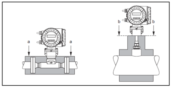
Diagrama del espesor máximo de aislamiento para T-mass 65F y 65I:
a. Espesor máximo de aislamiento para sensor de brida
b. Espesor máximo de aislamiento para sensor de inserción
III. Tramos rectos aguas arriba y aguas abajo del caudalímetro térmico
Las perturbaciones del estado del fluido tienen un impacto enorme en los instrumentos que miden según el principio de difusión térmica. Generalmente, el caudalímetro térmico debe instalarse lo más lejos posible de la fuente de perturbación. Para más detalles, consulte la norma ISO 14511.
- Cuando existan dos o más fuentes de perturbación aguas arriba del caudalímetro, se debe cumplir con la longitud recomendada de tramo recto aguas arriba de la fuente de perturbación más fuerte. Por ejemplo: si hay una válvula instalada antes de un codo de tubería, la longitud de tramo recto requerida entre la válvula y el caudalímetro debe ser de 50 x DN.
- Al medir gases extremadamente ligeros (por ejemplo: helio e hidrógeno), todas las longitudes de tramo recto aguas arriba deben duplicarse.
Longitud mínima recomendada de tramos rectos aguas arriba y aguas abajo (sin regulador de flujo):
Sensor de brida
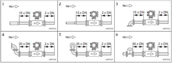
1=Reducción; 2=Ampliación; 3=Codo de 90° o tubería en T; 4=2x codo de 90°; 5=2x codo de 90° (3 direcciones); 6=Válvula de control
Sensor de inserción
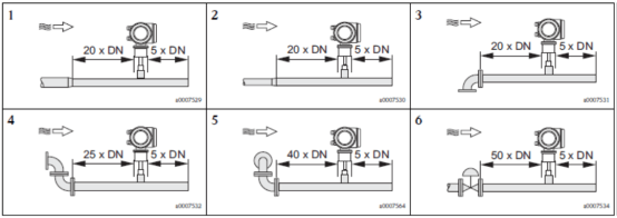
1=Reducción; 2=Ampliación; 3=Codo de 90° o tubería en T; 4=2x codo de 90°; 5=2x codo de 90° (3 direcciones); 6=Válvula de control o regulador de presión
Requisitos generales de instalación para caudalímetros másicos térmicos (reducción, ampliación y codo de 90° o tubería en T):
| Tipo de sensor | Longitud de tramo recto aguas arriba | Longitud de tramo recto aguas abajo |
|---|---|---|
| Sensor de brida | 15 x DN | 2 x DN |
| Sensor de inserción | 20 x DN | 5 x DN |
IV. Regulador de flujo con placa de orificio
Cuando no se puedan cumplir los requisitos de longitud de tramos rectos aguas arriba y aguas abajo, se recomienda instalar un regulador de flujo con placa de orificio.
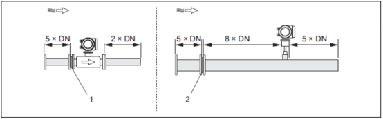
1 = Regulador de flujo para sensor de brida; 2 = Regulador de flujo para sensor de inserción
Regulador de flujo para sensor de inserción 65I
Rango de diámetro de aplicación de DN 80 .. 300 mm (3...12"). El regulador de flujo debe instalarse en la tubería aguas arriba del sensor, con una longitud de tramo recto aguas arriba de 8 x DN. El propio regulador de flujo requiere además 5 x DN de tramo recto aguas arriba.
Regulador de flujo para sensor de brida 65F
Sensor t-mass F de diseño especial de Endress+Hauser (diámetros de DN 25 .. 100 (1' ... 4")). Ofrece múltiples tipos de orificios de montaje y dimensiones de instalación; una placa de orificio puede satisfacer simultáneamente los requisitos de diferentes clases de brida (por ejemplo: CI. 150 y CI. 300).
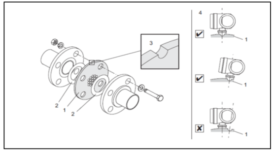
Instalación del regulador de flujo:
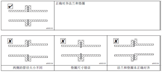
El regulador de flujo y la junta deben coincidir con las dos bridas de tubería y la brida del caudalímetro. Solo se permiten tuercas de montaje que coincidan con los orificios de los pernos de la brida, para garantizar un posicionamiento correcto. La ranura de posicionamiento debe estar en el mismo plano horizontal que el transmisor. Una instalación incorrecta del regulador de flujo tiene un impacto mínimo en la precisión de medición.
1=Regulador de flujo con placa de orificio; 2=Anillo de sellado/junta; 3=Ranura de posicionamiento; 4=Ranura de calibración en el mismo plano que el transmisor
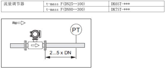
Longitud del tramo recto aguas abajo con medición de presión: el punto de medición de presión debe instalarse en la tubería aguas abajo del instrumento de medición, para garantizar que la conexión de proceso del transmisor de presión no afecte el flujo que entra en el punto de medición.
¡Atención!
- Para optimizar el rendimiento de medición, se recomienda pedir simultáneamente el sensor t-mass F y el regulador de flujo, para que ambos puedan calibrarse al mismo tiempo. Así el impacto en el rendimiento de medición es mínimo.
- Al medir con otros tipos de reguladores de flujo que no sean de Endress+Hauser junto con el sensor t-mass F, el estado del fluido y la caída de presión en la tubería pueden afectar el rendimiento de medición.
- Los pernos, tuercas, anillos de sellado, etc. no son piezas de suministro estándar y deben ser proporcionados por el usuario.
V. Requisitos del sistema de tuberías
- La tubería de conexión debe tener el mismo diámetro interior que el caudalímetro; la desviación máxima del diámetro de tubería no debe exceder:
- Diámetro < DN 200 (8"): 1 mm (0.04 pulgadas)
- Diámetro ≥ DN 200 (8"): 3 mm (0.12 pulgadas)
- Al reinstalar, no deben generarse partículas metálicas ni partículas abrasivas, para evitar dañar los elementos sensores durante el arranque.
VI. Orientación de instalación del caudalímetro másico térmico
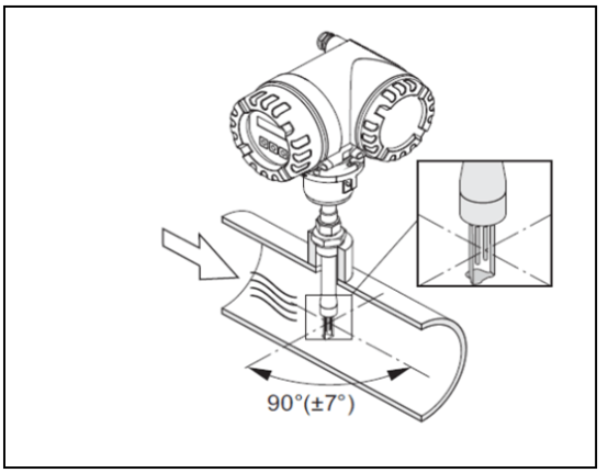
Asegúrese de que la flecha del sensor apunte en la misma dirección que el flujo de gas en la tubería.
De brida
De inserción
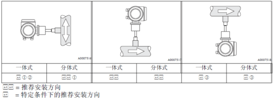
① Al medir gases saturados o gases impuros, se recomienda una orientación de instalación en tubería vertical con flujo hacia arriba, para reducir el efecto de condensación o contaminación.
② En entornos con vibraciones severas o instalación inestable, no se recomienda esta orientación de instalación.
③ Solo aplicable a la medición de gases limpios/secos. Para medir gases muy húmedos o gases saturados de agua (por ejemplo: biogás), no instale el sensor desde la parte inferior de una tubería horizontal. Debe adoptarse la orientación de instalación en tubería inclinada como se muestra en la figura siguiente (a = 135°).
VII. Instalación del sensor de inserción
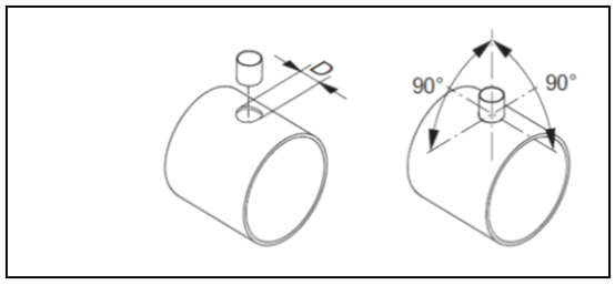
Condiciones de instalación del asiento de soldadura:
¡Cuidado!
Al instalar en tuberías rectangulares de pared delgada, utilice un soporte de sensor adecuado.
D = Ø31.0mm±0.5 mm (Ø1.22"±0.019")
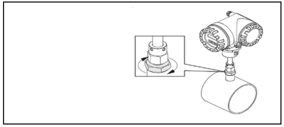
Ajuste de la posición del sensor de inserción:
Inserte el sensor en el asiento de soldadura, apriete a mano la tuerca inferior del manguito de fijación, luego use una llave (42 mm) para apretar 1/4 de vuelta.
¡Cuidado!
- Rosca NPT: use cinta selladora de rosca o sellador
- Rosca G1A: debe instalarse el anillo de sellado (pieza de suministro estándar)
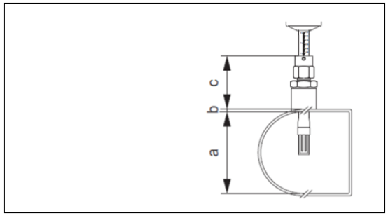
Cálculo de la profundidad de inserción:
a. Diámetro interior de tubería circular. Cuando el sensor se instala verticalmente, la altura de la tubería rectangular; cuando el sensor se instala horizontalmente, el ancho de la tubería rectangular. (a = mín. 80 mm o 3")
Cálculo de la profundidad de inserción: (0.3 x a) + b + c + 2 mm
(Profundidad de inserción = (0.3 x A) + B + (C1 + C2) + 0.079 pulgadas)
b. Espesor de pared de tubería
c. Profundidad del tubo corto soldado en la tubería, incluida la conexión de tubería del sensor y el kit de instalación para reemplazo en línea (opcional).
La longitud mínima requerida para el sensor de inserción puede calcularse mediante el software de selección Applicator de Endress+Hauser (versión 10.02 o posterior) o mediante los siguientes pasos. La longitud mínima requerida para el sensor de inserción depende de la profundidad de inserción requerida. El valor calculado de profundidad de inserción debe estar dentro del rango ajustable del sensor de inserción correspondiente.
1. Determine las dimensiones A, B, C1 y C2
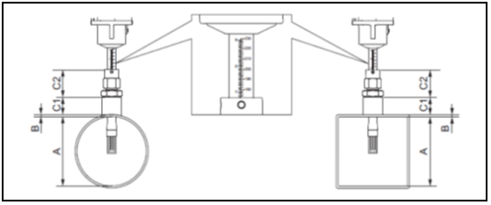
A = Tubería circular: diámetro interior de tubería (DN); tubería/canal rectangular: dimensión interior
B = Espesor de pared de tubería o espesor de canal
C1 + C2 = Longitud del conjunto de montaje y longitud del tubo de inserción del manguito de fijación
Al calcular la profundidad de inserción mediante el menú "Configuración rápida" del sensor, se requieren los siguientes parámetros:


2. Calcule la profundidad de inserción: Profundidad de inserción = (0.3 x A) + B + (C1 + C2) + 2 mm
3. Compare el valor calculado de profundidad de inserción con los valores de parámetros de la tabla siguiente para obtener la profundidad de inserción adecuada del sensor de inserción. ¡El valor calculado de profundidad de inserción debe estar dentro del rango ajustable del sensor de inserción correspondiente!
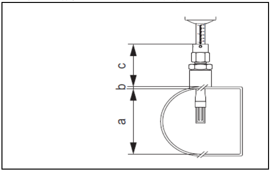
Ajuste del valor calculado de profundidad de inserción:
- Apriete la tuerca superior del manguito de fijación, asegurándose de que aún se pueda ajustar la posición del sensor.
- Ajuste la posición del sensor según el valor calculado de profundidad de inserción.
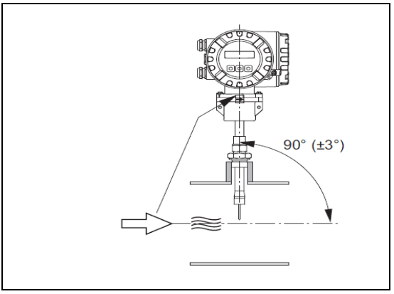
Ajuste la dirección de inserción del sensor de inserción con referencia a la dirección del flujo:
Verifique y confirme que la orientación de instalación del sensor en la tubería esté a 90° con respecto a la dirección del flujo; gire el sensor para que la flecha del sensor apunte en la misma dirección que el flujo.
Fijación del sensor de inserción:
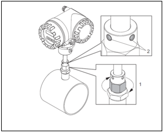
- Apriete a mano el manguito de fijación (1) para fijar el sensor. Luego, use una llave de boca (36 mm) para apretar 1/4 de vuelta más en sentido horario.
- Apriete los dos tornillos de fijación (4), (llave hexagonal de 3 mm; 1/8"). ¡Advertencia! Tenga en cuenta el par de apriete: 4 Nm (2.95 lbf ft)
- Verifique que el sensor y el transmisor ya no giren.
- Bajo la presión de trabajo máxima, verifique si hay fugas en el punto de medición.
VIII. Guía de instalación del transmisor
Rotación de la carcasa de aluminio de campo: carcasa de aluminio de campo, adecuada para áreas no explosivas
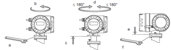
Carcasa de aluminio de campo, para zonas 1 o Cl. I Div. 1 en atmósferas explosivas
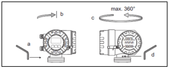
- Afloje el tornillo de fijación.
- Gire suavemente la carcasa del transmisor en sentido horario hasta la posición de tope (extremo de la rosca).
- Gire la carcasa del transmisor en sentido antihorario (máx. 360°) hasta la posición deseada.
- Vuelva a apretar el tornillo de fijación.
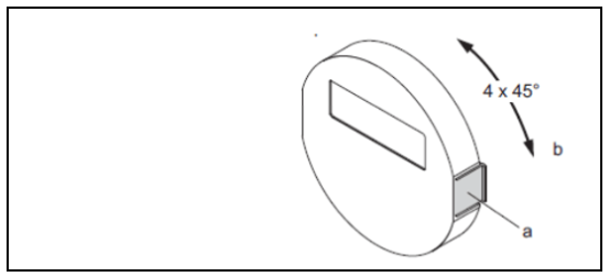
- Presione el clip lateral del módulo de visualización para desmontarlo de la tapa de la cámara electrónica.
- Gire el módulo de visualización a la posición deseada (ángulo máximo de rotación en ambas direcciones: 4x45°) y vuelva a instalarlo en la tapa de la cámara electrónica.