
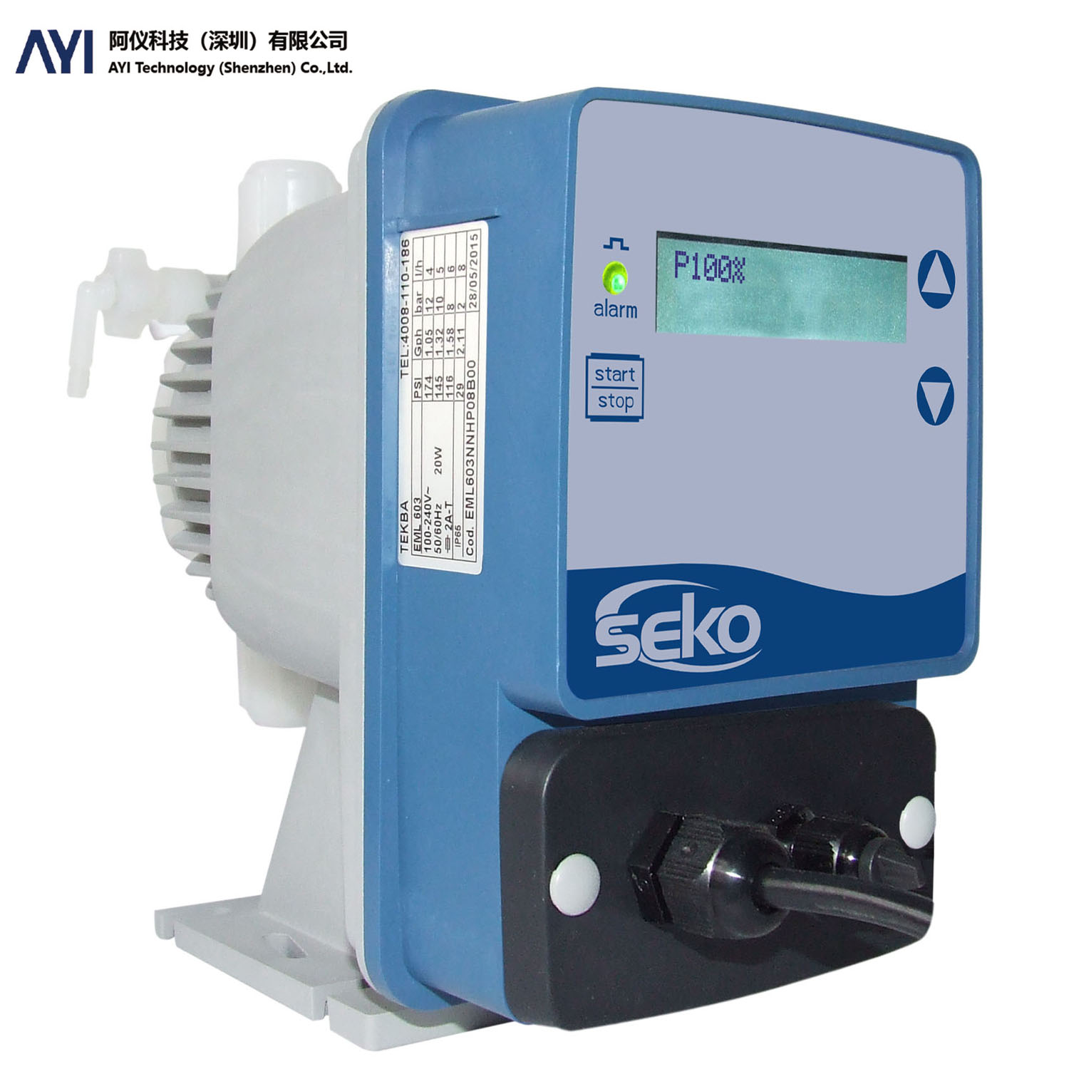
SEKO solenoid-driven diaphragm pump
SEKO-TEKBA Series
Digital display horizontal installation electromagnetic drive diaphragm pump
Tekba series is a microprocessor-based digital display solenoid-driven diaphragm pump with simple and stable operation. Includes five sub-series: EMS, EML, EMC, EMM and EMG.
- flow range: 2.5-110 liters/hour, maximum pressure 20bar
- contact end: PVDF (pump head), PTFE (diaphragm), EPDM or FPM (sealing ring) and ceramic (valve ball)
- EMS and EML flow can be adjusted manually, EMC,EMM and EMG flow can be adjusted manually and automatically, among which EMC can receive digital pulse signals; EMM can receive 4-20mA current signal; EMG is a multi-function model, which can choose a variety of automatic control methods.
Application areas
Municipal water and wastewater treatment, chlorine dioxide dosing and reverse osmosis, food, beverage and pharmaceutical industries, etc.
compatibility
PVDF pump head and ceramic ball valve are the standard configuration of the pump. The PVDF pump head is compatible with almost all chemicals used in industry, sewage treatment and drinking water. The use of ceramic ball valve improves the reliability of dosing and the chemical compatibility of the entire liquid contact end
reliable performance
After testing, the service life of the diaphragm is more than 5 years. Advanced design concepts and excellent manufacturing processes have created a long service life of the diaphragm. The diaphragm is made of pure solid PTFE material and can be compatible with most chemicals. The service life of the diaphragm is more than 5 years and no longer requires regular replacement of the diaphragm.
dosing mode
The flow can be adjusted manually or automatically (signal input control) EML,EMM and EMC also have a liquid level probe interface, manual exhaust valve can assist in starting the pump
Installation Method
Horizontal installation
| EMS: manual flow adjustment, manually adjust the flow pump run/stop LED indication through the buttons on the control panel to display the frequency percentage (P%) and the number of strokes (F) |
| EML: manual flow adjustment, with liquid level probe interface, manually adjust the flow pump run/stop LED indication through the button on the control panel, can display the frequency percentage (P%) and the number of strokes (F) with liquid level Probe interface |
|
EMC: Automatic flow adjustment, (digital pulse signal input), with operating status display, and liquid level probe interface. can choose the following two different dosing modes |
|
EMM: Automatic flow adjustment (4-20 mA current signal input), with operating status display, and liquid level probe interface. can choose two different modes of administration: |
| EMG: multi-function model, can choose a variety of automatic control mode |
| optional PTFE sealing ring |
| optional model with Modbus RTU RS485 interface |
|
optional models with wireless connectivity:
|
technical parameters:
| Series | |||||||||
| EMS | digital explicit | Flow Manual Adjustment | |||||||
| EML | flow manual adjustment, with liquid level probe interface | ||||||||
| EMC | Flow manual adjustment/automatic adjustment, with liquid level probe interface (controlled according to external digital pulse signal input) | ||||||||
| EMM | Flow manual adjustment/automatic adjustment, with liquid level probe interface (controlled according to external analog signal 4-20mA current signal input) | ||||||||
| EMG | Multi-function model, can choose a variety of automatic control mode | ||||||||
| Model | pressure | flow | stroke flow | Connecting pipe dimension inner/outer diameter [mm] | stroke frequency | power | gross weight | carton size | |
| [bar] | [l/h] | [ml/stroke] | [stroke/minute] | [tile] | [kg] | [length×width×height] [mm] | |||
| 600 | 20 | 2.5 | 0.35 | 4/6 suction 4/7 discharge | 120 | 20 | 3.9 | 285*250*210 | |
| 18 | 3 | 0.42 | |||||||
| 14 | 4.2 | 0.58 | |||||||
| 8 | 7 | 0.97 | |||||||
| 603 | 12 | 4 | 0.42 | 4/6 | 160 | 20 | 3.4 | ||
| 10 | 5 | 0.52 | |||||||
| 8 | 6 | 0.63 | |||||||
| 2 | 8 | 0.83 | |||||||
| 800 | 16 | 7 | 0.38 | 4/6 | 300 | 40 | 4.4 | ||
| 10 | 10 | 0.55 | |||||||
| 5 | 15 | 0.83 | |||||||
| 1 | 18 | 1 | |||||||
| 803 | 5 | 20 | 1.11 | 8/12 | 300 | 40 | 4.4 | ||
| 4 | 32 | 1.78 | |||||||
| 2 | 62 | 3.44 | |||||||
| 0.1 | 110 | 6.11 | |||||||
Model Code:
| Series | Tekba | |||||||||
| EMS | Flow Manual Adjustment | |||||||||
| EML | flow manual adjustment, with liquid level probe interface | |||||||||
| EMC | Manual flow adjustment/flow ratio adjustment, with liquid level probe port, through the external digital pulse signal to adjust the flow ratio | |||||||||
| EMM | Manual flow adjustment/flow ratio adjustment, with liquid level probe port, through external analog signal (0/4-20mA current signal) or digital pulse signal to adjust the flow ratio | |||||||||
| EMG | Multi-function model, can choose a variety of automatic control mode | |||||||||
| Model | pressure (bar) | flow (L/H) | stroke flow (ml/stroke) |
Connecting pipe size Inner diameter/outer diameter (mm) |
maximum frequency (stroke/minute) |
power (W) | weight (KG) | carton size Length X Width X Height (mm) |
||
| 600 | 20 | 2.5 | 0.35 | 4/6 suction 4/7 discharge | 120 | 20 | 3.9 | 290X255X220 | ||
| 18 | 3 | 0.42 | ||||||||
| 14 | 4.2 | 0.58 | ||||||||
| 8 | 7 | 0.97 | ||||||||
| 603 | 12 | 4 | 0.42 | 4/6 | 160 | 20 | 3.4 | |||
| 10 | 5 | 0.52 | ||||||||
| 8 | 6 | 0.63 | ||||||||
| 2 | 8 | 0.83 | ||||||||
| 800 | 16 | 7 | 0.38 | 4/6 | 300 | 40 | 4.4 | |||
| 10 | 10 | 0.55 | ||||||||
| 5 | 15 | 0.83 | ||||||||
| 1 | 18 | 1 | ||||||||
| 803 | 5 | 20 | 1.11 | 8/12 | 300 | 40 | 4.4 | |||
| 4 | 32 | 1.78 | ||||||||
| 2 | 62 | 3.44 | ||||||||
| 0.1 | 110 | 6.11 | ||||||||
| stroke length adjustment | ||||||||||
| N | monotone (stroke frequency) | |||||||||
| power supply | ||||||||||
| N | 100-240Vac,50/60Hz | |||||||||
| Material of touch end | pump head | valve ball | diaphragm | |||||||
| H | PVDF | ceramic | PTFE | |||||||
| Installation accessories | ||||||||||
| P | PVDF | |||||||||
| sealing ring | ||||||||||
| 0 | FPM | |||||||||
| 1 | EPDM | |||||||||
| 2 | PTFE | |||||||||
| color | Rear | Front | ||||||||
| 8 | standard | RAL7004 | RAL5010 | |||||||
| Signal Interface | ||||||||||
| 0 | standard | |||||||||
| W | WIFI | |||||||||
| M | Modbus RTU RS485 | |||||||||
| customization | ||||||||||
| 0 | standard | |||||||||
| EML | 600 | N | N | H | P | 0 | 8 | 0 | 0 | |
Case Studies
Municipal Wastewater Treatment · TEKBA — Application Case
Customer Profile
The typical setting in Municipal Wastewater Treatment is the inlet, biological and outlet stages of a municipal plant. The measuring point is TEKBA; the focus is basic solenoid diaphragm dosing with the TEKBA range.
Key Difficulties
Conditions are high solids and corrosive fractions, with large diurnal flow swings and, on top of that, effluent parameters drift and probes foul with sludge and biofilm, which a standard configuration cannot handle for long. The design therefore starts with selected by minimum dosing rate, back pressure and adjustment method.
Implementation
The scope ran through the solenoid diaphragm series: selecting for solenoid-driven diaphragm dosing behaviour. Technically it hinges on selected by minimum dosing rate, back pressure and adjustment method, and on these requirements: stable compliance with Grade 1A discharge limits and online data reporting.
Customer Benefit
In practice this means simple and easy to service, well suited to small and mid-size water systems, which cut the workload on the site maintenance team.
Food & Beverage · TEKBA — Application Case
Project Background
The project covers dosing, pasteurising, filling and CIP stages. The work centres on TEKBA and the core task is basic solenoid diaphragm dosing with the TEKBA range.
Operating Challenges
The medium and duty are characterised by syrups, dairy and beverages that scale easily, under strict hygienic requirements, and frequent cleaning demands instruments that withstand hot CIP/SIP caustic cycles. So TEKBA cannot be specified generically — it calls for selected by minimum dosing rate, back pressure and adjustment method.
Solution
The Ainstru engineering team worked through the solenoid diaphragm series: selecting for solenoid-driven diaphragm dosing behaviour. The configuration involves selected by minimum dosing rate, back pressure and adjustment method, with these requirements in view: food-safety and hygienic design per 3-A / EHEDG.
Results
Since start-up the system has run steadily; the practical result is simple and easy to service, well suited to small and mid-size water systems.
Chemical & Pharmaceutical · TEKBA — Application Case
Project Overview
The site is reactors, metering vessels and finished-product tanks. The customer wanted TEKBA properly configured on the existing plant, with the aim of basic solenoid diaphragm dosing with the TEKBA range.
Technical Challenges
What actually causes trouble is highly corrosive media with solvents and crystallisation, partly in explosive atmospheres, and corrosion plus Ex protection shortens instrument life and makes downtime costly. All of this means the TEKBA configuration has to involve selected by minimum dosing rate, back pressure and adjustment method.
Configuration
Supply and installation were organised through the solenoid diaphragm series: selecting for solenoid-driven diaphragm dosing behaviour. On site this meant selected by minimum dosing rate, back pressure and adjustment method, checked line by line against: Ex certification and GMP traceability of records.
Performance
After commissioning the outcome is simple and easy to service, well suited to small and mid-size water systems, and the readings are now used for process tuning.
Power & Energy · TEKBA — Application Case
Site Conditions
This is a Power & Energy customer whose plant is at boiler feedwater, turbine condensate and FGD/DeNOx systems. The main task was basic solenoid diaphragm dosing with the TEKBA range.
The Problem
The difficulty lies in high temperature and pressure with both steam and saline water; at the same time drift under high temperature and pressure, with very costly unplanned outages. Specification therefore means selected by minimum dosing rate, back pressure and adjustment method.
What We Did
We took a solenoid diaphragm series approach — selecting for solenoid-driven diaphragm dosing behaviour. Delivery was built around selected by minimum dosing rate, back pressure and adjustment method, with point-by-point checks on: compliance with power-industry codes and unit availability targets.
Operating Outcome
In service the system performs as intended — simple and easy to service, well suited to small and mid-size water systems, with routine maintenance falling noticeably.