

Advantages
- DN 15 … DN 300 (½" … 12")
- Short production lead times
- The most commonly used flowmeter in the chemical and process industries, with PTFE/PFA liner and Hastelloy electrodes.
- Excellent chemical resistance
- All global certifications for use in hazardous areas:
- ATEX, FM, CSA, IEcEx
- 24 V and 115/230 V Ex, compact and remote versions
- Intrinsically safe ia analog output
- Extensive self-diagnostics, error indication and fault logging
- The fully welded construction enhances the wear resistance of the instrument, making it suitable for demanding applications.
- The SENSORPROM unit automatically updates the configuration parameters for easy commissioning
- MAG 6000 I, fully compliant with NAMUR requirements
Complies with NE 21, NE 32, NE 43, NE 53 and NE70
Application
SITRANS F M electromagnetic flow sensors are mainly used in the following areas:
- Chemical industry
- Process industry
- Pulp and paper
- Industrial wastewater
Design
- Compact or remote installation possible
- Transmitter, easy “plug and play” type, flexible application
- High-temperature sensor, application temperature up to 150 ℃
- Complies with EEC standards: PED, EN 1092-1 flange and CRN 97/23/EC pressure directive
- Built-in length complies with ISO 13359 standard
- Field upgradeable to IP68/NEMA 6P for standard sensors.
Mode of operation
The flow measurement principle is based on Faraday's law of electromagnetic induction; the sensor converts the flow signal into a voltage signal proportional to the fluid velocity.
Integration
A complete flowmeter consists of a flow sensor and the associated MAG 5000, 6000 or 6000 I transmitter.
The flexible communication concept USM II simplifies the integration and upgrade of the flowmeter with many different bus systems. These bus systems include: HART, FOUNDATION Fieldbus H1, DeviceNet, PROFIBUS DP and PA, Modbus RTU/RS 485.
Pressure - temperature curves according to EN (DIN) flange, material A 105 carbon steel
Pressure-temperature curves according to ANSI B16.5 flange
Note: The pressure - temperature curves are only intended to assist with system selection. No responsibility is taken for the accuracy of the information. For accurate data, please refer to the PED requirements.
Technical specifications
|
Version |
MAG 3100 P |
|---|---|
|
Product features |
For the chemical and process industries (including in fast transfer schedules |
|
Nominal size |
|
|
|
|
Measuring principle |
Electromagnetic induction |
|
Excitation frequency (power supply: 50 Hz/60 Hz) |
|
|
|
|
|
|
Process connection |
|
|
Flange |
EN 1092 -1, raised face1) (EN 1092-1, DIN 2501 & BS 4504 have the same mating dimensions) |
|
|
|
|
|
|
|
ANSI B16.5 (~BS 1560), raised face |
|
|
|
|
Rated operating conditions |
|
|
Ambient temperature (ambient also depends on linear characteristics) |
|
|
-40 … +100 °C (-40 … +212 °F) |
|
-20 … +60 °C (-4 … +140 °F) |
|
|
|
-20 … +60 °C (-4 … +140 °F) |
|
-20 … +60 °C (-4 … +140 °F) |
|
-20 … +60 °C (-4 … +140 °F) |
|
Operating pressure [abs.bar] (maximum operating pressure decreases with increasing operating temperature and when stainless steel flanges are selected) |
|
|
|
|
|
|
|
|
Enclosure pressure rating |
IP67 according to EN 60529/NEMA 4X/6 (1 mH2O, 30 min) |
|
Option: IP68 ~ EN 60529/NEMA 6P, 10 mH2O continuous (non-Ex) |
|
|
Pressure loss at 3 m/s |
Same as straight pipe |
|
Pressure test |
1.5 times rated pressure |
|
Mechanical load (vibration) |
|
|
|
|
|
|
|
|
Medium temperature |
|
|
|
|
EMC |
2014/30/EU |
|
Design |
|
|
Weight |
See dimensional drawing |
|
Flange and enclosure material |
Carbon steel ASTM A 105, with anti-corrosion coating (corrosivity category C4, according to ISO 12944-2) |
|
Electrode material |
PTFE:Hastelloy C276/2.4819 |
|
PFA:Hastelloy C22/2.4602 |
|
|
Grounding electrode material |
PTFE:no grounding electrode |
|
PFA:Hastelloy |
|
|
Terminal box (remote version) |
|
|
|
|
|
|
Cable entries |
|
|
|
|
|
|
|
|
|
|
Certifications and approvals |
|
|
Calibration |
|
|
Zero point, 2 x 25 % and 2 x 90 % |
|
Hazardous area |
|
|
|
|
|
|
Pressure equipment |
PED, CRN |
|
Other |
|
1) DN ≤ 600 type 01 (SORF); DN > 600 type 11 (WNRF)
2) Compact version only
Dimensional drawing
MAG 3100 P sensor, with compact or remote transmitter
Dimensions in: [mm]
Metric
|
DN |
A1) |
A1 |
A2 |
B |
D1 |
L2) |
TE3) |
TF3) |
Weight 4) |
|||
|
EN 1092-1-201 |
ANSI 16.5 |
|||||||||||
|
PN 10 |
PN 16 |
PN 40 |
Class 150 |
|||||||||
|
[mm] |
[mm] |
[mm] |
[mm] |
[mm] |
[mm] |
[mm] |
[mm] |
[mm] |
[mm] |
[mm] |
[mm] |
[kg] |
|
15 |
187 |
341 |
338 |
59 |
104 |
- |
- |
200 |
200 |
6 |
2 |
4 |
|
25 |
187 |
341 |
338 |
59 |
104 |
- |
- |
200 |
200 |
6 |
2 |
5 |
|
40 |
197 |
351 |
348 |
82 |
124 |
- |
- |
200 |
200 |
6 |
2 |
8 |
|
50 |
205 |
359 |
356 |
72 |
139 |
- |
- |
200 |
200 |
6 |
2 |
9 |
|
65 |
212 |
369 |
366 |
72 |
154 |
- |
200/- |
- |
200 |
6 |
2 |
11 |
|
80 |
222 |
376 |
373 |
72 |
174 |
- |
200/- |
- |
2725) |
6 |
2 |
12 |
|
100 |
242 |
396 |
393 |
85 |
214 |
- |
250/- |
- |
250 |
6 |
2 |
16 |
|
125 |
255 |
409 |
406 |
85 |
239 |
- |
250/- |
- |
250 |
6 |
2 |
19 |
|
150 |
276 |
430 |
427 |
85 |
282 |
- |
300/- |
- |
300 |
6 |
2 |
27 |
|
200 |
304 |
458 |
455 |
137 |
338 |
350 |
350/- |
- |
350 |
8 |
2 |
40 |
|
250 |
332 |
486 |
483 |
157 |
393 |
450 |
450/- |
- |
450 |
8 |
2 |
60 |
|
300 |
357 |
511 |
508 |
157 |
444 |
500 |
500/- |
- |
500 |
8 |
2 |
80 |
1) When a stainless steel terminal box is used, the length is reduced by 14.5 mm (Ex, high-temperature version)
2) When grounding rings are used, the flange thickness and gasket thickness must be added to the built-in length.
3) TE = grounding ring type E, TF = grounding ring, flat ring
4) The weights indicated are at PN 16, without transmitter
5) Does not comply with standard ISO 13359
- indicates not available for this model
D= flange outside diameter, see flange table
MAG 3100 P sensor, with compact or remote transmitter
Imperial
|
DN |
A1) |
A1 |
A2 |
B |
D1 |
L2) |
TE3) |
TF3) |
Weight 4) |
|||
|
EN 1092-1-201 |
ANSI 16.5 |
|||||||||||
|
PN 10 |
PN 16 |
PN 40 |
Class 150 |
|||||||||
|
[inch] |
[inch] |
[inch] |
[inch] |
[inch] |
[inch] |
[inch] |
[inch] |
[inch] |
[inch] |
[inch] |
[inch] |
[lbs] |
|
½ |
7.36 |
13.4 |
13.34 |
2.32 |
4.09 |
- |
- |
7.87 |
7.87 |
0.24 |
0.08 |
9 |
|
1 |
7.36 |
13.4 |
13.34 |
2.32 |
4.09 |
- |
- |
7.87 |
7.87 |
0.24 |
0.08 |
11 |
|
1½ |
7.76 |
13.8 |
13.74 |
3.23 |
4.88 |
- |
- |
7.87 |
7.87 |
0.24 |
0.08 |
17 |
|
2 |
8.07 |
14.1 |
14.04 |
2.83 |
5.47 |
- |
- |
7.87 |
7.87 |
0.24 |
0.08 |
20 |
|
2½ |
8.35 |
14.4 |
14.34 |
2.83 |
6.06 |
- |
7.87/- |
- |
7.87 |
0.24 |
0.08 |
24 |
|
3 |
8.74 |
14.8 |
14.74 |
2.83 |
6.85 |
- |
7.87/- |
- |
10.715) |
0.24 |
0.08 |
26 |
|
4 |
9.53 |
15.6 |
15.54 |
3.35 |
8.43 |
- |
9.84/- |
- |
9.84 |
0.24 |
0.08 |
35 |
|
5 |
10.04 |
16.1 |
16.04 |
3.35 |
9.41 |
- |
9.84/- |
- |
9.84 |
0.24 |
0.08 |
42 |
|
6 |
10.87 |
16.9 |
16.84 |
3.35 |
11.10 |
- |
11.81/- |
- |
11.81 |
0.24 |
0.08 |
60 |
|
8 |
11.97 |
18.0 |
17.94 |
5.39 |
13.31 |
13.78 |
13.78/- |
- |
13.78 |
0.31 |
0.08 |
88 |
|
10 |
13.07 |
19.1 |
19.04 |
6.18 |
15.47 |
17.72 |
17.72/- |
- |
17.72 |
0.31 |
0.08 |
132 |
|
12 |
14.05 |
20.1 |
20.04 |
6.18 |
17.48 |
19.69 |
19.69/- |
- |
19.69 |
0.31 |
0.08 |
176 |
1) When using a stainless steel terminal box, the length is reduced by 0.571 ft (Ex, high-temperature version)
2) When using grounding rings, the flange thickness and gasket thickness must be added to the insertion length.
3) TE = grounding ring type E, TF = grounding ring, flat ring
4) Weight applicable to ANSI 150 without transmitter.
5) Does not comply with standard ISO 13359
D= flange outer diameter, see flange table
Source: Siemens website public information
Casos de servicio
Tratamiento de Aguas Residuales Municipales — Caudalímetro electromagnético: caso de aplicación
Situación en planta
Se trata de un cliente del sector Tratamiento de Aguas Residuales Municipales cuya planta está en las etapas de entrada, biológica y salida de una planta municipal. La tarea principal era caudal volumétrico de líquidos conductivos.
El problema
La dificultad está en alto contenido de sólidos y componentes corrosivos, con grandes variaciones diarias de caudal; a la vez, los parámetros del efluente oscilan y las sondas se ensucian con lodos y biopelícula. Por eso la especificación implica elegir combinación de revestimiento y electrodo según conductividad, sólidos y abrasión.
Qué hicimos
Adoptamos un enfoque de caudal: solución de caudal adaptada a diámetro, medio y rango. La entrega se construyó en torno a elegir combinación de revestimiento y electrodo según conductividad, sólidos y abrasión; se verificó punto por punto: cumplimiento estable del nivel 1A y reporte de datos en línea.
Resultado operativo
En servicio el sistema responde a lo previsto: sin obstrucción: mínima pérdida de carga y bajo mantenimiento, con un mantenimiento rutinario notablemente menor.
Alimentación y Bebidas — Caudalímetro electromagnético: caso de aplicación
Contexto de aplicación
las etapas de dosificación, pasteurización, llenado y limpieza CIP es un servicio típico de Alimentación y Bebidas. El proyecto partió de Caudalímetro electromagnético, centrándose en caudal volumétrico de líquidos conductivos.
Limitaciones del proceso
las limpiezas frecuentes exigen instrumentos resistentes a ciclos CIP/SIP con sosa caliente, y jarabes, lácteos y bebidas proclives a incrustaciones, con estrictos requisitos higiénicos no hace sino acentuarlo. Por eso la especificación de Caudalímetro electromagnético debe cubrir elegir combinación de revestimiento y electrodo según conductividad, sólidos y abrasión.
Enfoque de suministro
La entrega se gestionó como caudal: solución de caudal adaptada a diámetro, medio y rango. La ejecución se centró en elegir combinación de revestimiento y electrodo según conductividad, sólidos y abrasión, junto con requisitos de seguridad alimentaria y diseño higiénico 3-A / EHEDG.
Resultados en campo
La operación evidencia el beneficio: sin obstrucción: mínima pérdida de carga y bajo mantenimiento, con una confianza claramente mayor en este punto de medición.
Química y Farmacéutica — Caudalímetro electromagnético: caso de aplicación
Perfil del cliente
El entorno típico en Química y Farmacéutica es reactores, vasijas de dosificación y tanques de producto terminado. El punto de medición es Caudalímetro electromagnético; el foco es caudal volumétrico de líquidos conductivos.
Dificultades clave
Las condiciones son medios muy corrosivos con disolventes y cristalización, en parte en atmósferas explosivas y, encima, la corrosión y la protección Ex acortan la vida útil y encarecen las paradas, algo que una configuración estándar no soporta mucho tiempo. El diseño parte de elegir combinación de revestimiento y electrodo según conductividad, sólidos y abrasión.
Implementación
El alcance se canalizó por la vía de caudal: solución de caudal adaptada a diámetro, medio y rango. Técnicamente se apoya en elegir combinación de revestimiento y electrodo según conductividad, sólidos y abrasión, y en estos requisitos: certificación Ex y trazabilidad de datos según GMP.
Beneficio para el cliente
En la práctica esto significa sin obstrucción: mínima pérdida de carga y bajo mantenimiento, lo que redujo la carga del equipo de mantenimiento.
Energía y Electricidad — Caudalímetro electromagnético: caso de aplicación
Antecedentes del proyecto
El proyecto abarca agua de alimentación, condensado de turbina y sistemas de desulfuración/DeNOx. El trabajo se centra en Caudalímetro electromagnético y la tarea principal es caudal volumétrico de líquidos conductivos.
Condiciones de servicio
El medio y el servicio se caracterizan por alta temperatura y presión, con vapor y agua salina, y además deriva a alta temperatura y presión, con paradas no programadas muy costosas. Por eso Caudalímetro electromagnético no puede especificarse de forma genérica: requiere elegir combinación de revestimiento y electrodo según conductividad, sólidos y abrasión.
Solución
El equipo técnico de Ainstru trabajó por la vía de caudal: solución de caudal adaptada a diámetro, medio y rango. La configuración incluye elegir combinación de revestimiento y electrodo según conductividad, sólidos y abrasión; se cuidaron estos requisitos: cumplimiento de normativas del sector y objetivos de disponibilidad.
Resultados
Desde la puesta en marcha el sistema funciona de forma estable; el resultado práctico es sin obstrucción: mínima pérdida de carga y bajo mantenimiento.
Recomendados similares
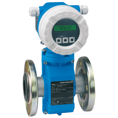 Endress+Hauser
Caudalímetro electromagnético
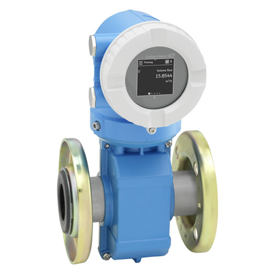 Endress+Hauser
Caudalímetro electromagnético 10
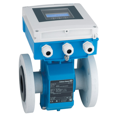 Endress+Hauser
Caudalímetro electromagnético
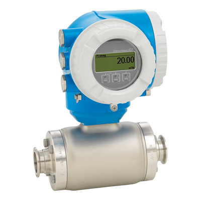 Endress+Hauser
Caudalímetro electromagnético
 Endress+Hauser
Caudalímetro electromagnético con alimentación por batería
 Endress+Hauser
MAGPHANT
 Endress+Hauser
Caudalímetro electromagnético
 Endress+Hauser