

Advantages
- DN 15 … DN 300 (½" … 12")
- Short production lead times
- The most commonly used flowmeter in the chemical and process industries, with PTFE/PFA liner and Hastelloy electrodes.
- Excellent chemical resistance
- All global certifications for use in hazardous areas:
- ATEX, FM, CSA, IEcEx
- 24 V and 115/230 V Ex, compact and remote versions
- Intrinsically safe ia analog output
- Extensive self-diagnostics, error indication and fault logging
- The fully welded construction enhances the wear resistance of the instrument, making it suitable for demanding applications.
- The SENSORPROM unit automatically updates the configuration parameters for easy commissioning
- MAG 6000 I, fully compliant with NAMUR requirements
Complies with NE 21, NE 32, NE 43, NE 53 and NE70
Application
SITRANS F M electromagnetic flow sensors are mainly used in the following areas:
- Chemical industry
- Process industry
- Pulp and paper
- Industrial wastewater
Design
- Compact or remote installation possible
- Transmitter, easy “plug and play” type, flexible application
- High-temperature sensor, application temperature up to 150 ℃
- Complies with EEC standards: PED, EN 1092-1 flange and CRN 97/23/EC pressure directive
- Built-in length complies with ISO 13359 standard
- Field upgradeable to IP68/NEMA 6P for standard sensors.
Mode of operation
The flow measurement principle is based on Faraday's law of electromagnetic induction; the sensor converts the flow signal into a voltage signal proportional to the fluid velocity.
Integration
A complete flowmeter consists of a flow sensor and the associated MAG 5000, 6000 or 6000 I transmitter.
The flexible communication concept USM II simplifies the integration and upgrade of the flowmeter with many different bus systems. These bus systems include: HART, FOUNDATION Fieldbus H1, DeviceNet, PROFIBUS DP and PA, Modbus RTU/RS 485.
Pressure - temperature curves according to EN (DIN) flange, material A 105 carbon steel
Pressure-temperature curves according to ANSI B16.5 flange
Note: The pressure - temperature curves are only intended to assist with system selection. No responsibility is taken for the accuracy of the information. For accurate data, please refer to the PED requirements.
Technical specifications
|
Version |
MAG 3100 P |
|---|---|
|
Product features |
For the chemical and process industries (including in fast transfer schedules |
|
Nominal size |
|
|
|
|
Measuring principle |
Electromagnetic induction |
|
Excitation frequency (power supply: 50 Hz/60 Hz) |
|
|
|
|
|
|
Process connection |
|
|
Flange |
EN 1092 -1, raised face1) (EN 1092-1, DIN 2501 & BS 4504 have the same mating dimensions) |
|
|
|
|
|
|
|
ANSI B16.5 (~BS 1560), raised face |
|
|
|
|
Rated operating conditions |
|
|
Ambient temperature (ambient also depends on linear characteristics) |
|
|
-40 … +100 °C (-40 … +212 °F) |
|
-20 … +60 °C (-4 … +140 °F) |
|
|
|
-20 … +60 °C (-4 … +140 °F) |
|
-20 … +60 °C (-4 … +140 °F) |
|
-20 … +60 °C (-4 … +140 °F) |
|
Operating pressure [abs.bar] (maximum operating pressure decreases with increasing operating temperature and when stainless steel flanges are selected) |
|
|
|
|
|
|
|
|
Enclosure pressure rating |
IP67 according to EN 60529/NEMA 4X/6 (1 mH2O, 30 min) |
|
Option: IP68 ~ EN 60529/NEMA 6P, 10 mH2O continuous (non-Ex) |
|
|
Pressure loss at 3 m/s |
Same as straight pipe |
|
Pressure test |
1.5 times rated pressure |
|
Mechanical load (vibration) |
|
|
|
|
|
|
|
|
Medium temperature |
|
|
|
|
EMC |
2014/30/EU |
|
Design |
|
|
Weight |
See dimensional drawing |
|
Flange and enclosure material |
Carbon steel ASTM A 105, with anti-corrosion coating (corrosivity category C4, according to ISO 12944-2) |
|
Electrode material |
PTFE:Hastelloy C276/2.4819 |
|
PFA:Hastelloy C22/2.4602 |
|
|
Grounding electrode material |
PTFE:no grounding electrode |
|
PFA:Hastelloy |
|
|
Terminal box (remote version) |
|
|
|
|
|
|
Cable entries |
|
|
|
|
|
|
|
|
|
|
Certifications and approvals |
|
|
Calibration |
|
|
Zero point, 2 x 25 % and 2 x 90 % |
|
Hazardous area |
|
|
|
|
|
|
Pressure equipment |
PED, CRN |
|
Other |
|
1) DN ≤ 600 type 01 (SORF); DN > 600 type 11 (WNRF)
2) Compact version only
Dimensional drawing
MAG 3100 P sensor, with compact or remote transmitter
Dimensions in: [mm]
Metric
|
DN |
A1) |
A1 |
A2 |
B |
D1 |
L2) |
TE3) |
TF3) |
Weight 4) |
|||
|
EN 1092-1-201 |
ANSI 16.5 |
|||||||||||
|
PN 10 |
PN 16 |
PN 40 |
Class 150 |
|||||||||
|
[mm] |
[mm] |
[mm] |
[mm] |
[mm] |
[mm] |
[mm] |
[mm] |
[mm] |
[mm] |
[mm] |
[mm] |
[kg] |
|
15 |
187 |
341 |
338 |
59 |
104 |
- |
- |
200 |
200 |
6 |
2 |
4 |
|
25 |
187 |
341 |
338 |
59 |
104 |
- |
- |
200 |
200 |
6 |
2 |
5 |
|
40 |
197 |
351 |
348 |
82 |
124 |
- |
- |
200 |
200 |
6 |
2 |
8 |
|
50 |
205 |
359 |
356 |
72 |
139 |
- |
- |
200 |
200 |
6 |
2 |
9 |
|
65 |
212 |
369 |
366 |
72 |
154 |
- |
200/- |
- |
200 |
6 |
2 |
11 |
|
80 |
222 |
376 |
373 |
72 |
174 |
- |
200/- |
- |
2725) |
6 |
2 |
12 |
|
100 |
242 |
396 |
393 |
85 |
214 |
- |
250/- |
- |
250 |
6 |
2 |
16 |
|
125 |
255 |
409 |
406 |
85 |
239 |
- |
250/- |
- |
250 |
6 |
2 |
19 |
|
150 |
276 |
430 |
427 |
85 |
282 |
- |
300/- |
- |
300 |
6 |
2 |
27 |
|
200 |
304 |
458 |
455 |
137 |
338 |
350 |
350/- |
- |
350 |
8 |
2 |
40 |
|
250 |
332 |
486 |
483 |
157 |
393 |
450 |
450/- |
- |
450 |
8 |
2 |
60 |
|
300 |
357 |
511 |
508 |
157 |
444 |
500 |
500/- |
- |
500 |
8 |
2 |
80 |
1) When a stainless steel terminal box is used, the length is reduced by 14.5 mm (Ex, high-temperature version)
2) When grounding rings are used, the flange thickness and gasket thickness must be added to the built-in length.
3) TE = grounding ring type E, TF = grounding ring, flat ring
4) The weights indicated are at PN 16, without transmitter
5) Does not comply with standard ISO 13359
- indicates not available for this model
D= flange outside diameter, see flange table
MAG 3100 P sensor, with compact or remote transmitter
Imperial
|
DN |
A1) |
A1 |
A2 |
B |
D1 |
L2) |
TE3) |
TF3) |
Weight 4) |
|||
|
EN 1092-1-201 |
ANSI 16.5 |
|||||||||||
|
PN 10 |
PN 16 |
PN 40 |
Class 150 |
|||||||||
|
[inch] |
[inch] |
[inch] |
[inch] |
[inch] |
[inch] |
[inch] |
[inch] |
[inch] |
[inch] |
[inch] |
[inch] |
[lbs] |
|
½ |
7.36 |
13.4 |
13.34 |
2.32 |
4.09 |
- |
- |
7.87 |
7.87 |
0.24 |
0.08 |
9 |
|
1 |
7.36 |
13.4 |
13.34 |
2.32 |
4.09 |
- |
- |
7.87 |
7.87 |
0.24 |
0.08 |
11 |
|
1½ |
7.76 |
13.8 |
13.74 |
3.23 |
4.88 |
- |
- |
7.87 |
7.87 |
0.24 |
0.08 |
17 |
|
2 |
8.07 |
14.1 |
14.04 |
2.83 |
5.47 |
- |
- |
7.87 |
7.87 |
0.24 |
0.08 |
20 |
|
2½ |
8.35 |
14.4 |
14.34 |
2.83 |
6.06 |
- |
7.87/- |
- |
7.87 |
0.24 |
0.08 |
24 |
|
3 |
8.74 |
14.8 |
14.74 |
2.83 |
6.85 |
- |
7.87/- |
- |
10.715) |
0.24 |
0.08 |
26 |
|
4 |
9.53 |
15.6 |
15.54 |
3.35 |
8.43 |
- |
9.84/- |
- |
9.84 |
0.24 |
0.08 |
35 |
|
5 |
10.04 |
16.1 |
16.04 |
3.35 |
9.41 |
- |
9.84/- |
- |
9.84 |
0.24 |
0.08 |
42 |
|
6 |
10.87 |
16.9 |
16.84 |
3.35 |
11.10 |
- |
11.81/- |
- |
11.81 |
0.24 |
0.08 |
60 |
|
8 |
11.97 |
18.0 |
17.94 |
5.39 |
13.31 |
13.78 |
13.78/- |
- |
13.78 |
0.31 |
0.08 |
88 |
|
10 |
13.07 |
19.1 |
19.04 |
6.18 |
15.47 |
17.72 |
17.72/- |
- |
17.72 |
0.31 |
0.08 |
132 |
|
12 |
14.05 |
20.1 |
20.04 |
6.18 |
17.48 |
19.69 |
19.69/- |
- |
19.69 |
0.31 |
0.08 |
176 |
1) When using a stainless steel terminal box, the length is reduced by 0.571 ft (Ex, high-temperature version)
2) When using grounding rings, the flange thickness and gasket thickness must be added to the insertion length.
3) TE = grounding ring type E, TF = grounding ring, flat ring
4) Weight applicable to ANSI 150 without transmitter.
5) Does not comply with standard ISO 13359
D= flange outer diameter, see flange table
Source: Siemens website public information
Case Studies
Municipal Wastewater Treatment · Electromagnetic flow meter — Application Case
Site Conditions
This is a Municipal Wastewater Treatment customer whose plant is at the inlet, biological and outlet stages of a municipal plant. The main task was volumetric flow of conductive liquids.
The Problem
The difficulty lies in high solids and corrosive fractions, with large diurnal flow swings; at the same time effluent parameters drift and probes foul with sludge and biofilm. Specification therefore means choosing liner and electrode pairing by conductivity, solids and abrasion.
What We Did
We took a flow range approach — flow solution matched to line size, medium and range. Delivery was built around choosing liner and electrode pairing by conductivity, solids and abrasion, with point-by-point checks on: stable compliance with Grade 1A discharge limits and online data reporting.
Operating Outcome
In service the system performs as intended — no obstruction, so pressure loss is minimal and upkeep low, with routine maintenance falling noticeably.
Food & Beverage · Electromagnetic flow meter — Application Case
Application Context
dosing, pasteurising, filling and CIP stages is a typical Food & Beverage duty. The project started from Electromagnetic flow meter, focusing on volumetric flow of conductive liquids.
Process Constraints
frequent cleaning demands instruments that withstand hot CIP/SIP caustic cycles, and syrups, dairy and beverages that scale easily, under strict hygienic requirements only amplify it. The Electromagnetic flow meter specification must therefore cover choosing liner and electrode pairing by conductivity, solids and abrasion.
Delivery Approach
Delivery was handled as the flow range — flow solution matched to line size, medium and range. Execution centred on choosing liner and electrode pairing by conductivity, solids and abrasion, together with food-safety and hygienic design per 3-A / EHEDG.
Field Results
Operation shows the benefit clearly — no obstruction, so pressure loss is minimal and upkeep low, with confidence in this measuring point improving markedly.
Chemical & Pharmaceutical · Electromagnetic flow meter — Application Case
Customer Profile
The typical setting in Chemical & Pharmaceutical is reactors, metering vessels and finished-product tanks. The measuring point is Electromagnetic flow meter; the focus is volumetric flow of conductive liquids.
Key Difficulties
Conditions are highly corrosive media with solvents and crystallisation, partly in explosive atmospheres and, on top of that, corrosion plus Ex protection shortens instrument life and makes downtime costly, which a standard configuration cannot handle for long. The design therefore starts with choosing liner and electrode pairing by conductivity, solids and abrasion.
Implementation
The scope ran through the flow range: flow solution matched to line size, medium and range. Technically it hinges on choosing liner and electrode pairing by conductivity, solids and abrasion, and on these requirements: Ex certification and GMP traceability of records.
Customer Benefit
In practice this means no obstruction, so pressure loss is minimal and upkeep low, which cut the workload on the site maintenance team.
Power & Energy · Electromagnetic flow meter — Application Case
Project Background
The project covers boiler feedwater, turbine condensate and FGD/DeNOx systems. The work centres on Electromagnetic flow meter and the core task is volumetric flow of conductive liquids.
Operating Challenges
The medium and duty are characterised by high temperature and pressure with both steam and saline water, and drift under high temperature and pressure, with very costly unplanned outages. So Electromagnetic flow meter cannot be specified generically — it calls for choosing liner and electrode pairing by conductivity, solids and abrasion.
Solution
The Ainstru engineering team worked through the flow range: flow solution matched to line size, medium and range. The configuration involves choosing liner and electrode pairing by conductivity, solids and abrasion, with these requirements in view: compliance with power-industry codes and unit availability targets.
Results
Since start-up the system has run steadily; the practical result is no obstruction, so pressure loss is minimal and upkeep low.
Related Products
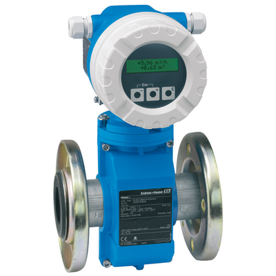 Endress+Hauser
Electromagnetic flowmeter
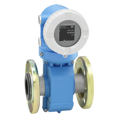 Endress+Hauser
Electromagnetic flowmeter 10
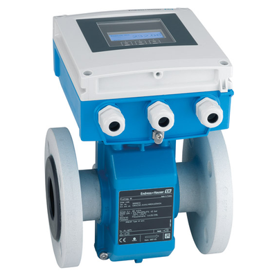 Endress+Hauser
Electromagnetic flowmeter
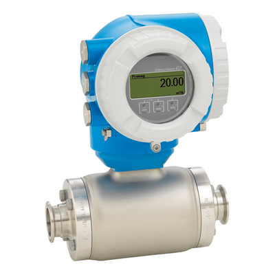 Endress+Hauser
Electromagnetic flowmeter
 Endress+Hauser
Battery-powered electromagnetic flowmeter
 Endress+Hauser
MAGPHANT
 Endress+Hauser
Electromagnetic flowmeter
 Endress+Hauser