

Advantages
- Sensor size: DN 10 to DN 100 (3/8" to 4")
- AISI 316 stainless steel housing
- Sensor: hygienic connections, 3A certified and EHEDG certified
- Hygienic design compliant with CIP/SIP cleaning standards
- SENSORPROM memory unit automatically updates configuration parameters for easy commissioning
- Housing protection class IP67/NEMA 4X
- Patented built-in verifier operates using SENSORPROM signature technology
Application
SITRANS F M electromagnetic sensors are mainly used in the following areas:
- Food industry
- Beverage industry
- Pharmaceutical industry
Design
- Unique mechanical design with a large number of user-customizable hygienic connections
- Compact or remote installation, “plug and play”, flexible application
- Easy on-site upgrade to IP68/NEMA 6P terminal box
- ATEX 2G D type (ceramic liner) suitable for hazardous areas
Operating mode
The flow measurement principle is based on Faraday's law of electromagnetic induction. The sensor converts the flow signal into a voltage signal proportional to the fluid velocity.
Integration
A complete flowmeter consists of the sensor and the associated SITRANS F M 5000, 6000 and 6000 I transmitters. The flexible communication concept USM II simplifies the integration and upgrade of the flowmeter with many different bus systems. These bus systems include: HART, FOUNDATION Fieldbus H1, DeviceNet, PROFIBUS DP and PA, Modbus RTU/RS 485.
Pressure/temperature curve; material AISI 316L/1.4404
Pressure/temperature curve; material AISI 316L/1.4404
Technical specifications
|
Measuring principle |
Electromagnetic induction |
|
Excitation frequency (power supply: 50 Hz/60 Hz) |
DN 10 … 65 (¼" … 2½"):12.5 Hz/15 Hz |
|
Process connections |
|
|
Nominal size |
DN 10 … DN 100 (3/8" … 4") |
|
Process connections |
Hygienic connections are available in the following mounting types: |
|
|
|
|
|
|
|
Rated operating conditions |
|
|
Ambient Conditions |
|
|
Ambient temperature |
|
|
-40 … +100 °C (-40 … +212 °F) |
|
-20 … +60 °C (-4 … +140 °F) |
|
-20 … +60 °C (-4 … +140 °F) |
|
-20 … +60 °C (-4 … +140 °F) |
|
-10 … +60 °C (14 … 140 °F) |
|
Medium temperature |
|
|
MAG 1100 F (ceramic) |
-20 … +150 ºC (-4 … +302 ºF) |
|
MAG 1100 F (PFA) |
-30 … +130 °C (-22 … +266 °F) |
|
Temperature shock |
|
|
MAG 1100 F |
|
|
|
|
|
|
|
|
MAG 1100 F (PFA) |
Max. ±100 ºC (212 °F) instantaneous |
|
Operating pressure |
|
|
MAG 1100 F (ceramic) |
DN 10 … 65:40 bar (3/8" … 2½":580 psi) |
|
Vacuum: 1 x 10⁻⁶ barabs (1.5 x 10⁻⁵ psiabs) |
|
|
MAG 1100 F (PFA) |
20 bar (290 psi) |
|
Vacuum: 0.02 barabs (0.3 psiabs) |
|
|
DN 80 … DN 100:CO2 max. pressure 7 bar (101.5 psi) |
|
|
Mechanical load (vibration) |
18 … 1 000 Hz, random, 2 hours, x, y, z in all directions according to EN 60068-2-36 |
|
Sensor: 3.17 g RMS |
|
|
Sensor with compact MAG 5000/6000 transmitter: 3.17 grms |
|
|
Sensor with compact MAG 6000 I/MAG 6000 I Ex mounted transmitter: 1.14 grms |
|
|
For compact mounting of MAG 6000 I/MAG 6000 I Ex, a bracket should be used to support the transmitter to avoid stress on the sensor components. |
|
|
Housing pressure rating |
IP67 according to EN 60529 (NEMA 4X), 1 mH2O, 30 minutes |
|
EMC |
2014/30/EU |
|
Design |
|
|
Weight |
See dimensional drawing |
|
Material |
|
|
Housing |
|
|
Stainless steel AISI 316L/1.4404 |
|
Terminal box (remote version) |
|
|
Glass fiber reinforced polyamide |
|
Stainless steel AISI 316/1.4436, |
|
Stainless steel AISI 316/1.4436, |
|
Liner |
|
|
MAG 1100 F (ceramic) |
Aluminum oxide Al2O3 (ceramic) |
|
MAG 1100 F (PFA) |
Reinforced PFA (PTFE) (non-Ex) |
|
Electrodes |
|
|
MAG 1100 F (ceramic) |
Platinum and gold/titanium copper alloy |
|
MAG 1100 F (PFA) |
|
|
|
|
Cable entries |
|
|
|
|
|
|
|
|
|
|
Certifications and approvals |
|
|
Calibration |
|
|
Zero point, 2 x 25 %, 2 x 90 % |
|
Hazardous area |
|
|
|
|
|
|
|
|
|
|
|
|
Hygienic |
|
|
|
|
|
|
Pressure equipment |
PED - 2014/68/EU |
|
Other |
|
Accessories
|
Welding adapter |
|
|
Connection for direct welding to dairy pipes, stainless steel 1.4404 |
Tri-Weld ISO 2037, DIN 11850, SMS 3008, BS 4825‑1 |
|
PN 40 (600 psi) |
|
PN 25 (350 psi) |
|
Clamp connection |
Tri-Clamp, ISO 2852, DIN 32676, SMS 3016, BS 4825‑3 |
|
DN 10, 15, 25, 40 and 50 (3/8", ½", 1", 1½" and 2") |
PN 16 (200 psi) |
|
DN 65, 80 and 100 (2½", 3" and 4") |
PN 10 (150 psi) |
|
Threaded connection |
|
|
DIN 11851 |
|
|
PN 40 (600 psi) |
|
PN 25 (350 psi) |
|
ISO 2853, BS 4825-4 |
|
|
PN 16 (200 psi) |
|
SMS 1145 |
|
|
PN 6 (80 psi) |
|
Design |
|
|
Material |
|
|
Adapter |
Stainless steel AISI 316/1.4436, |
|
Gasket |
|
|
FKM/FPM with stainless steel insert (AISI 304/1.4301) (‑20 … +150 °C (-4 … +302 °F)) |
|
EPDM (-20 … +150 °C (-4 … +302 °F)) |
|
|
EPDM (-20 … +150 °C (-4 … +302 °F)) |
|
NBR (-20 … +100 °C (-4 … +212 °F)) |
Note:
When the connection is attached to the sensor, the operating pressure is lower than the pressure allowed for the connection.
Dimensional drawing
Sensor MAG 1100 F, compact/remote version
Dimensions in: [mm]
Important note: For compact mounting with MAG 6000 I/Ex – the transmitter must be supported to avoid sensor stress.
|
Size |
L |
A |
A1 3) |
B 2) |
B1 |
D |
Di (Al2O3) |
Di PFA |
Weight 1) |
|---|---|---|---|---|---|---|---|---|---|
|
10 |
64 |
161 |
315 |
193.7 |
344.7 |
64.0 |
10 |
10 |
2.2 |
|
15 |
64 |
161 |
315 |
193.7 |
344.7 |
64.0 |
15 |
16 |
2.2 |
|
25 |
79 |
169 |
323 |
207.5 |
359.0 |
77.5 |
25 |
26 |
2.7 |
|
40 |
94 |
179 |
333 |
228.0 |
379.0 |
91.0 |
40 |
38 |
3.4 |
|
50 |
104 |
188 |
342 |
247.7 |
398.7 |
119.0 |
50 |
50 |
4.2 |
|
65 |
131 |
197.5 |
351 |
262.6 |
413.6 |
130.0 |
65 |
66 |
5.5 |
|
80 |
156 |
204 |
357 |
281.0 |
432.0 |
155.0 |
80 |
81 |
7.0 |
|
100 |
186 |
217 |
370 |
308.0 |
459.0 |
183.0 |
100 |
100 |
10.0 |
|
Size |
L |
A |
A1 3) |
B 2) |
B1 |
D |
Di (Al2O3) |
Di PFA |
Weight 1) |
|---|---|---|---|---|---|---|---|---|---|
|
3/8 |
2.52 |
6.34 |
12.40 |
7.62 |
13.57 |
2.52 |
0.39 |
0.39 |
4.8 |
|
½ |
2.52 |
6.34 |
12.40 |
7.62 |
13.57 |
2.52 |
0.59 |
0.63 |
4.8 |
|
1 |
3.11 |
6.66 |
12.72 |
8.17 |
14.13 |
3.05 |
0.98 |
1.02 |
4.9 |
|
1½ |
3.70 |
7.05 |
13.11 |
8.98 |
14.92 |
3.58 |
1.57 |
1.50 |
7.5 |
|
2 |
4.09 |
7.40 |
13.47 |
9.75 |
15.70 |
4.68 |
1.97 |
1.97 |
9.2 |
|
2½ |
5.16 |
7.78 |
13.82 |
10.34 |
16.28 |
5.12 |
2.56 |
2.60 |
12.0 |
|
3 |
6.14 |
8.03 |
14.06 |
11.06 |
17.01 |
6.10 |
3.15 |
3.19 |
15.0 |
|
4 |
7.32 |
8.54 |
14.57 |
12.13 |
18.07 |
7.20 |
3.94 |
3.94 |
22.0 |
1) When the MAG 5000 or MAG 6000 compact transmitter is installed, the weight increases by approx. 0.8 kg (1.8 lb),
when the MAG 6000 I transmitter is installed, the weight increases by approx. 5.5 kg ( 12.1 lbs).
2) When a stainless steel terminal box is used, the length is reduced by 14.5 mm (0.571") (always Ex version)
3) A2 is 3 mm (0.12") shorter than A1
MAG 1100 F sensor compact/remote — Insertion length
|
Size |
A |
L 1) |
|||
|---|---|---|---|---|---|
|
DN |
Inch |
[mm] |
[inch] |
[mm] |
[inch] |
|
10 |
3/8 |
99 |
3.90 |
146 |
5.75 |
|
15 |
½ |
99 |
3.90 |
146 |
5.75 |
|
25 |
1 |
113 |
4.45 |
161 |
6.34 |
|
40 |
1½ |
126 |
4.96 |
176 |
6.93 |
|
50 |
2 |
154 |
6.06 |
186 |
7.32 |
|
65 |
2½ |
165 |
6.50 |
223 |
8.78 |
|
80 |
3 |
200 |
7.87 |
258 |
10.16 |
|
100 |
4 |
225 |
8.86 |
288 |
11.34 |
1) The total insertion length “L” is independent of the selected connection type.
Source:Siemens website public information
Casos de servicio
Tratamiento de Aguas Residuales Municipales — Caudalímetro electromagnético: caso de aplicación
Situación en planta
Se trata de un cliente del sector Tratamiento de Aguas Residuales Municipales cuya planta está en las etapas de entrada, biológica y salida de una planta municipal. La tarea principal era caudal volumétrico de líquidos conductivos.
El problema
La dificultad está en alto contenido de sólidos y componentes corrosivos, con grandes variaciones diarias de caudal; a la vez, los parámetros del efluente oscilan y las sondas se ensucian con lodos y biopelícula. Por eso la especificación implica elegir combinación de revestimiento y electrodo según conductividad, sólidos y abrasión.
Qué hicimos
Adoptamos un enfoque de caudal: solución de caudal adaptada a diámetro, medio y rango. La entrega se construyó en torno a elegir combinación de revestimiento y electrodo según conductividad, sólidos y abrasión; se verificó punto por punto: cumplimiento estable del nivel 1A y reporte de datos en línea.
Resultado operativo
En servicio el sistema responde a lo previsto: sin obstrucción: mínima pérdida de carga y bajo mantenimiento, con un mantenimiento rutinario notablemente menor.
Alimentación y Bebidas — Caudalímetro electromagnético: caso de aplicación
Contexto de aplicación
las etapas de dosificación, pasteurización, llenado y limpieza CIP es un servicio típico de Alimentación y Bebidas. El proyecto partió de Caudalímetro electromagnético, centrándose en caudal volumétrico de líquidos conductivos.
Limitaciones del proceso
las limpiezas frecuentes exigen instrumentos resistentes a ciclos CIP/SIP con sosa caliente, y jarabes, lácteos y bebidas proclives a incrustaciones, con estrictos requisitos higiénicos no hace sino acentuarlo. Por eso la especificación de Caudalímetro electromagnético debe cubrir elegir combinación de revestimiento y electrodo según conductividad, sólidos y abrasión.
Enfoque de suministro
La entrega se gestionó como caudal: solución de caudal adaptada a diámetro, medio y rango. La ejecución se centró en elegir combinación de revestimiento y electrodo según conductividad, sólidos y abrasión, junto con requisitos de seguridad alimentaria y diseño higiénico 3-A / EHEDG.
Resultados en campo
La operación evidencia el beneficio: sin obstrucción: mínima pérdida de carga y bajo mantenimiento, con una confianza claramente mayor en este punto de medición.
Química y Farmacéutica — Caudalímetro electromagnético: caso de aplicación
Perfil del cliente
El entorno típico en Química y Farmacéutica es reactores, vasijas de dosificación y tanques de producto terminado. El punto de medición es Caudalímetro electromagnético; el foco es caudal volumétrico de líquidos conductivos.
Dificultades clave
Las condiciones son medios muy corrosivos con disolventes y cristalización, en parte en atmósferas explosivas y, encima, la corrosión y la protección Ex acortan la vida útil y encarecen las paradas, algo que una configuración estándar no soporta mucho tiempo. El diseño parte de elegir combinación de revestimiento y electrodo según conductividad, sólidos y abrasión.
Implementación
El alcance se canalizó por la vía de caudal: solución de caudal adaptada a diámetro, medio y rango. Técnicamente se apoya en elegir combinación de revestimiento y electrodo según conductividad, sólidos y abrasión, y en estos requisitos: certificación Ex y trazabilidad de datos según GMP.
Beneficio para el cliente
En la práctica esto significa sin obstrucción: mínima pérdida de carga y bajo mantenimiento, lo que redujo la carga del equipo de mantenimiento.
Energía y Electricidad — Caudalímetro electromagnético: caso de aplicación
Antecedentes del proyecto
El proyecto abarca agua de alimentación, condensado de turbina y sistemas de desulfuración/DeNOx. El trabajo se centra en Caudalímetro electromagnético y la tarea principal es caudal volumétrico de líquidos conductivos.
Condiciones de servicio
El medio y el servicio se caracterizan por alta temperatura y presión, con vapor y agua salina, y además deriva a alta temperatura y presión, con paradas no programadas muy costosas. Por eso Caudalímetro electromagnético no puede especificarse de forma genérica: requiere elegir combinación de revestimiento y electrodo según conductividad, sólidos y abrasión.
Solución
El equipo técnico de Ainstru trabajó por la vía de caudal: solución de caudal adaptada a diámetro, medio y rango. La configuración incluye elegir combinación de revestimiento y electrodo según conductividad, sólidos y abrasión; se cuidaron estos requisitos: cumplimiento de normativas del sector y objetivos de disponibilidad.
Resultados
Desde la puesta en marcha el sistema funciona de forma estable; el resultado práctico es sin obstrucción: mínima pérdida de carga y bajo mantenimiento.
Recomendados similares
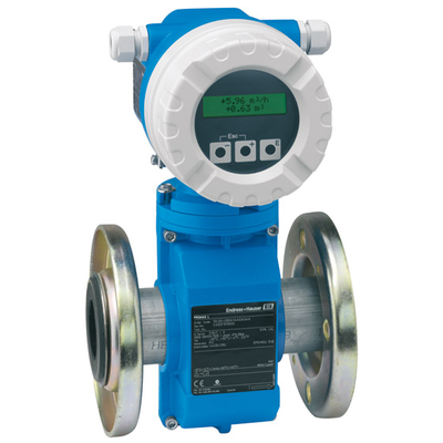 Endress+Hauser
Caudalímetro electromagnético
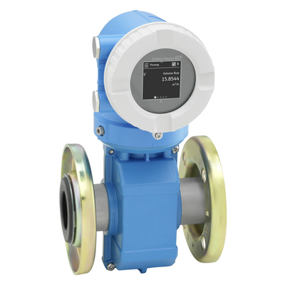 Endress+Hauser
Caudalímetro electromagnético 10
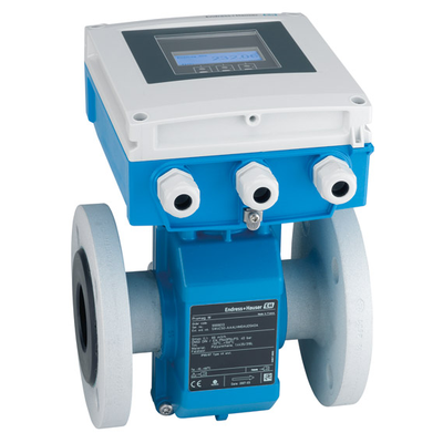 Endress+Hauser
Caudalímetro electromagnético
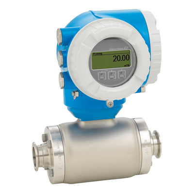 Endress+Hauser
Caudalímetro electromagnético
 Endress+Hauser
Caudalímetro electromagnético con alimentación por batería
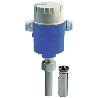 Endress+Hauser
MAGPHANT
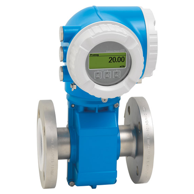 Endress+Hauser
Caudalímetro electromagnético
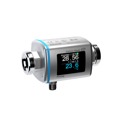 Endress+Hauser