

Advantages
- Sensor size: DN 10 to DN 100 (3/8" to 4")
- AISI 316 stainless steel housing
- Sensor: hygienic connections, 3A certified and EHEDG certified
- Hygienic design compliant with CIP/SIP cleaning standards
- SENSORPROM memory unit automatically updates configuration parameters for easy commissioning
- Housing protection class IP67/NEMA 4X
- Patented built-in verifier operates using SENSORPROM signature technology
Application
SITRANS F M electromagnetic sensors are mainly used in the following areas:
- Food industry
- Beverage industry
- Pharmaceutical industry
Design
- Unique mechanical design with a large number of user-customizable hygienic connections
- Compact or remote installation, “plug and play”, flexible application
- Easy on-site upgrade to IP68/NEMA 6P terminal box
- ATEX 2G D type (ceramic liner) suitable for hazardous areas
Operating mode
The flow measurement principle is based on Faraday's law of electromagnetic induction. The sensor converts the flow signal into a voltage signal proportional to the fluid velocity.
Integration
A complete flowmeter consists of the sensor and the associated SITRANS F M 5000, 6000 and 6000 I transmitters. The flexible communication concept USM II simplifies the integration and upgrade of the flowmeter with many different bus systems. These bus systems include: HART, FOUNDATION Fieldbus H1, DeviceNet, PROFIBUS DP and PA, Modbus RTU/RS 485.
Pressure/temperature curve; material AISI 316L/1.4404
Pressure/temperature curve; material AISI 316L/1.4404
Technical specifications
|
Measuring principle |
Electromagnetic induction |
|
Excitation frequency (power supply: 50 Hz/60 Hz) |
DN 10 … 65 (¼" … 2½"):12.5 Hz/15 Hz |
|
Process connections |
|
|
Nominal size |
DN 10 … DN 100 (3/8" … 4") |
|
Process connections |
Hygienic connections are available in the following mounting types: |
|
|
|
|
|
|
|
Rated operating conditions |
|
|
Ambient Conditions |
|
|
Ambient temperature |
|
|
-40 … +100 °C (-40 … +212 °F) |
|
-20 … +60 °C (-4 … +140 °F) |
|
-20 … +60 °C (-4 … +140 °F) |
|
-20 … +60 °C (-4 … +140 °F) |
|
-10 … +60 °C (14 … 140 °F) |
|
Medium temperature |
|
|
MAG 1100 F (ceramic) |
-20 … +150 ºC (-4 … +302 ºF) |
|
MAG 1100 F (PFA) |
-30 … +130 °C (-22 … +266 °F) |
|
Temperature shock |
|
|
MAG 1100 F |
|
|
|
|
|
|
|
|
MAG 1100 F (PFA) |
Max. ±100 ºC (212 °F) instantaneous |
|
Operating pressure |
|
|
MAG 1100 F (ceramic) |
DN 10 … 65:40 bar (3/8" … 2½":580 psi) |
|
Vacuum: 1 x 10⁻⁶ barabs (1.5 x 10⁻⁵ psiabs) |
|
|
MAG 1100 F (PFA) |
20 bar (290 psi) |
|
Vacuum: 0.02 barabs (0.3 psiabs) |
|
|
DN 80 … DN 100:CO2 max. pressure 7 bar (101.5 psi) |
|
|
Mechanical load (vibration) |
18 … 1 000 Hz, random, 2 hours, x, y, z in all directions according to EN 60068-2-36 |
|
Sensor: 3.17 g RMS |
|
|
Sensor with compact MAG 5000/6000 transmitter: 3.17 grms |
|
|
Sensor with compact MAG 6000 I/MAG 6000 I Ex mounted transmitter: 1.14 grms |
|
|
For compact mounting of MAG 6000 I/MAG 6000 I Ex, a bracket should be used to support the transmitter to avoid stress on the sensor components. |
|
|
Housing pressure rating |
IP67 according to EN 60529 (NEMA 4X), 1 mH2O, 30 minutes |
|
EMC |
2014/30/EU |
|
Design |
|
|
Weight |
See dimensional drawing |
|
Material |
|
|
Housing |
|
|
Stainless steel AISI 316L/1.4404 |
|
Terminal box (remote version) |
|
|
Glass fiber reinforced polyamide |
|
Stainless steel AISI 316/1.4436, |
|
Stainless steel AISI 316/1.4436, |
|
Liner |
|
|
MAG 1100 F (ceramic) |
Aluminum oxide Al2O3 (ceramic) |
|
MAG 1100 F (PFA) |
Reinforced PFA (PTFE) (non-Ex) |
|
Electrodes |
|
|
MAG 1100 F (ceramic) |
Platinum and gold/titanium copper alloy |
|
MAG 1100 F (PFA) |
|
|
|
|
Cable entries |
|
|
|
|
|
|
|
|
|
|
Certifications and approvals |
|
|
Calibration |
|
|
Zero point, 2 x 25 %, 2 x 90 % |
|
Hazardous area |
|
|
|
|
|
|
|
|
|
|
|
|
Hygienic |
|
|
|
|
|
|
Pressure equipment |
PED - 2014/68/EU |
|
Other |
|
Accessories
|
Welding adapter |
|
|
Connection for direct welding to dairy pipes, stainless steel 1.4404 |
Tri-Weld ISO 2037, DIN 11850, SMS 3008, BS 4825‑1 |
|
PN 40 (600 psi) |
|
PN 25 (350 psi) |
|
Clamp connection |
Tri-Clamp, ISO 2852, DIN 32676, SMS 3016, BS 4825‑3 |
|
DN 10, 15, 25, 40 and 50 (3/8", ½", 1", 1½" and 2") |
PN 16 (200 psi) |
|
DN 65, 80 and 100 (2½", 3" and 4") |
PN 10 (150 psi) |
|
Threaded connection |
|
|
DIN 11851 |
|
|
PN 40 (600 psi) |
|
PN 25 (350 psi) |
|
ISO 2853, BS 4825-4 |
|
|
PN 16 (200 psi) |
|
SMS 1145 |
|
|
PN 6 (80 psi) |
|
Design |
|
|
Material |
|
|
Adapter |
Stainless steel AISI 316/1.4436, |
|
Gasket |
|
|
FKM/FPM with stainless steel insert (AISI 304/1.4301) (‑20 … +150 °C (-4 … +302 °F)) |
|
EPDM (-20 … +150 °C (-4 … +302 °F)) |
|
|
EPDM (-20 … +150 °C (-4 … +302 °F)) |
|
NBR (-20 … +100 °C (-4 … +212 °F)) |
Note:
When the connection is attached to the sensor, the operating pressure is lower than the pressure allowed for the connection.
Dimensional drawing
Sensor MAG 1100 F, compact/remote version
Dimensions in: [mm]
Important note: For compact mounting with MAG 6000 I/Ex – the transmitter must be supported to avoid sensor stress.
|
Size |
L |
A |
A1 3) |
B 2) |
B1 |
D |
Di (Al2O3) |
Di PFA |
Weight 1) |
|---|---|---|---|---|---|---|---|---|---|
|
10 |
64 |
161 |
315 |
193.7 |
344.7 |
64.0 |
10 |
10 |
2.2 |
|
15 |
64 |
161 |
315 |
193.7 |
344.7 |
64.0 |
15 |
16 |
2.2 |
|
25 |
79 |
169 |
323 |
207.5 |
359.0 |
77.5 |
25 |
26 |
2.7 |
|
40 |
94 |
179 |
333 |
228.0 |
379.0 |
91.0 |
40 |
38 |
3.4 |
|
50 |
104 |
188 |
342 |
247.7 |
398.7 |
119.0 |
50 |
50 |
4.2 |
|
65 |
131 |
197.5 |
351 |
262.6 |
413.6 |
130.0 |
65 |
66 |
5.5 |
|
80 |
156 |
204 |
357 |
281.0 |
432.0 |
155.0 |
80 |
81 |
7.0 |
|
100 |
186 |
217 |
370 |
308.0 |
459.0 |
183.0 |
100 |
100 |
10.0 |
|
Size |
L |
A |
A1 3) |
B 2) |
B1 |
D |
Di (Al2O3) |
Di PFA |
Weight 1) |
|---|---|---|---|---|---|---|---|---|---|
|
3/8 |
2.52 |
6.34 |
12.40 |
7.62 |
13.57 |
2.52 |
0.39 |
0.39 |
4.8 |
|
½ |
2.52 |
6.34 |
12.40 |
7.62 |
13.57 |
2.52 |
0.59 |
0.63 |
4.8 |
|
1 |
3.11 |
6.66 |
12.72 |
8.17 |
14.13 |
3.05 |
0.98 |
1.02 |
4.9 |
|
1½ |
3.70 |
7.05 |
13.11 |
8.98 |
14.92 |
3.58 |
1.57 |
1.50 |
7.5 |
|
2 |
4.09 |
7.40 |
13.47 |
9.75 |
15.70 |
4.68 |
1.97 |
1.97 |
9.2 |
|
2½ |
5.16 |
7.78 |
13.82 |
10.34 |
16.28 |
5.12 |
2.56 |
2.60 |
12.0 |
|
3 |
6.14 |
8.03 |
14.06 |
11.06 |
17.01 |
6.10 |
3.15 |
3.19 |
15.0 |
|
4 |
7.32 |
8.54 |
14.57 |
12.13 |
18.07 |
7.20 |
3.94 |
3.94 |
22.0 |
1) When the MAG 5000 or MAG 6000 compact transmitter is installed, the weight increases by approx. 0.8 kg (1.8 lb),
when the MAG 6000 I transmitter is installed, the weight increases by approx. 5.5 kg ( 12.1 lbs).
2) When a stainless steel terminal box is used, the length is reduced by 14.5 mm (0.571") (always Ex version)
3) A2 is 3 mm (0.12") shorter than A1
MAG 1100 F sensor compact/remote — Insertion length
|
Size |
A |
L 1) |
|||
|---|---|---|---|---|---|
|
DN |
Inch |
[mm] |
[inch] |
[mm] |
[inch] |
|
10 |
3/8 |
99 |
3.90 |
146 |
5.75 |
|
15 |
½ |
99 |
3.90 |
146 |
5.75 |
|
25 |
1 |
113 |
4.45 |
161 |
6.34 |
|
40 |
1½ |
126 |
4.96 |
176 |
6.93 |
|
50 |
2 |
154 |
6.06 |
186 |
7.32 |
|
65 |
2½ |
165 |
6.50 |
223 |
8.78 |
|
80 |
3 |
200 |
7.87 |
258 |
10.16 |
|
100 |
4 |
225 |
8.86 |
288 |
11.34 |
1) The total insertion length “L” is independent of the selected connection type.
Source:Siemens website public information
Case Studies
Municipal Wastewater Treatment · Electromagnetic flow meter — Application Case
Site Conditions
This is a Municipal Wastewater Treatment customer whose plant is at the inlet, biological and outlet stages of a municipal plant. The main task was volumetric flow of conductive liquids.
The Problem
The difficulty lies in high solids and corrosive fractions, with large diurnal flow swings; at the same time effluent parameters drift and probes foul with sludge and biofilm. Specification therefore means choosing liner and electrode pairing by conductivity, solids and abrasion.
What We Did
We took a flow range approach — flow solution matched to line size, medium and range. Delivery was built around choosing liner and electrode pairing by conductivity, solids and abrasion, with point-by-point checks on: stable compliance with Grade 1A discharge limits and online data reporting.
Operating Outcome
In service the system performs as intended — no obstruction, so pressure loss is minimal and upkeep low, with routine maintenance falling noticeably.
Food & Beverage · Electromagnetic flow meter — Application Case
Application Context
dosing, pasteurising, filling and CIP stages is a typical Food & Beverage duty. The project started from Electromagnetic flow meter, focusing on volumetric flow of conductive liquids.
Process Constraints
frequent cleaning demands instruments that withstand hot CIP/SIP caustic cycles, and syrups, dairy and beverages that scale easily, under strict hygienic requirements only amplify it. The Electromagnetic flow meter specification must therefore cover choosing liner and electrode pairing by conductivity, solids and abrasion.
Delivery Approach
Delivery was handled as the flow range — flow solution matched to line size, medium and range. Execution centred on choosing liner and electrode pairing by conductivity, solids and abrasion, together with food-safety and hygienic design per 3-A / EHEDG.
Field Results
Operation shows the benefit clearly — no obstruction, so pressure loss is minimal and upkeep low, with confidence in this measuring point improving markedly.
Chemical & Pharmaceutical · Electromagnetic flow meter — Application Case
Customer Profile
The typical setting in Chemical & Pharmaceutical is reactors, metering vessels and finished-product tanks. The measuring point is Electromagnetic flow meter; the focus is volumetric flow of conductive liquids.
Key Difficulties
Conditions are highly corrosive media with solvents and crystallisation, partly in explosive atmospheres and, on top of that, corrosion plus Ex protection shortens instrument life and makes downtime costly, which a standard configuration cannot handle for long. The design therefore starts with choosing liner and electrode pairing by conductivity, solids and abrasion.
Implementation
The scope ran through the flow range: flow solution matched to line size, medium and range. Technically it hinges on choosing liner and electrode pairing by conductivity, solids and abrasion, and on these requirements: Ex certification and GMP traceability of records.
Customer Benefit
In practice this means no obstruction, so pressure loss is minimal and upkeep low, which cut the workload on the site maintenance team.
Power & Energy · Electromagnetic flow meter — Application Case
Project Background
The project covers boiler feedwater, turbine condensate and FGD/DeNOx systems. The work centres on Electromagnetic flow meter and the core task is volumetric flow of conductive liquids.
Operating Challenges
The medium and duty are characterised by high temperature and pressure with both steam and saline water, and drift under high temperature and pressure, with very costly unplanned outages. So Electromagnetic flow meter cannot be specified generically — it calls for choosing liner and electrode pairing by conductivity, solids and abrasion.
Solution
The Ainstru engineering team worked through the flow range: flow solution matched to line size, medium and range. The configuration involves choosing liner and electrode pairing by conductivity, solids and abrasion, with these requirements in view: compliance with power-industry codes and unit availability targets.
Results
Since start-up the system has run steadily; the practical result is no obstruction, so pressure loss is minimal and upkeep low.
Related Products
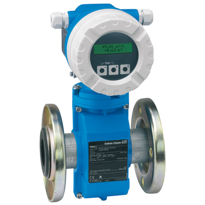 Endress+Hauser
Electromagnetic flowmeter
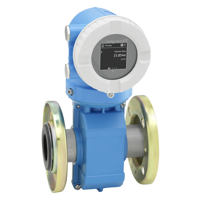 Endress+Hauser
Electromagnetic flowmeter 10
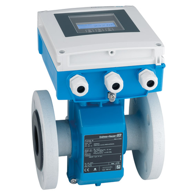 Endress+Hauser
Electromagnetic flowmeter
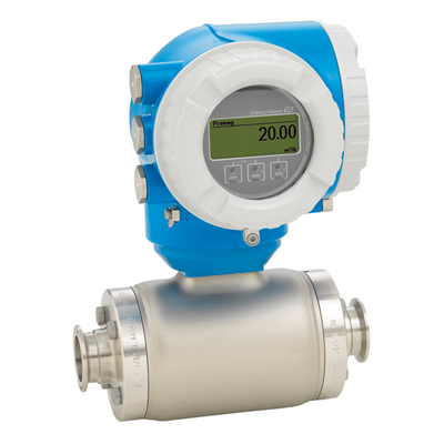 Endress+Hauser
Electromagnetic flowmeter
 Endress+Hauser
Battery-powered electromagnetic flowmeter
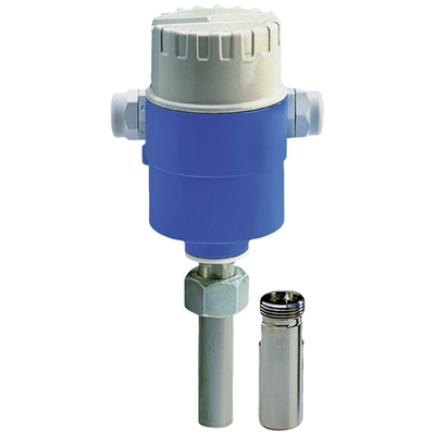 Endress+Hauser
MAGPHANT
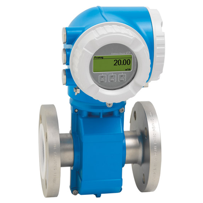 Endress+Hauser
Electromagnetic flowmeter
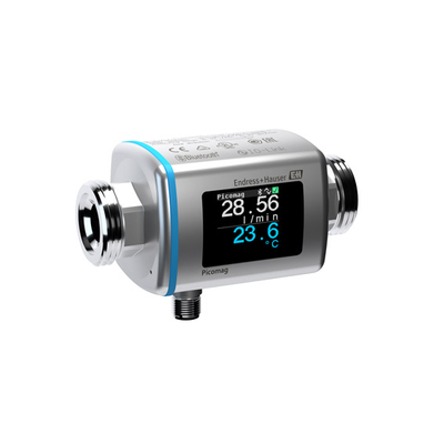 Endress+Hauser