
Technical Data
CompareGas
| Measuring Principle | Vortex |
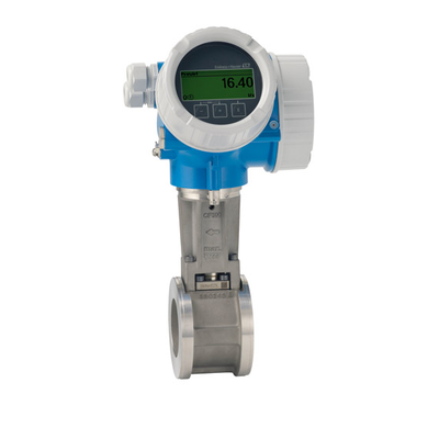
| Product headline | Cost-effective wafer flowmeter, available as compact or remote version. Integrated temperature measurement for mass/energy flow of saturated steam. For all basic applications and for 1-to-1 replacement of orifice plates. |
| Sensor features | Easy alignment of the sensor – included centering rings. High availability – proven robustness, resistance to vibrations, temperature shocks & water hammer. Long-term stability – robust drift-free capacitive sensor. Face-to-face length of 65 mm (2.56 in). No flanges. Low weight. |
| Transmitter features | Convenient device wiring – separate connection compartment. Safe operation – no need to open the device due to display with touch control, background lighting. Integrated verification – Heartbeat Technology. Display module with data transfer function. Robust dual-compartment housing. Plant safety: worldwide approvals (SIL, Haz. area). |
| Nominal diameter range | DN 15 to 150 (½ to 6") |
| Wetted materials | Measuring tube: 1.4408 (CF3M) DSC sensor: 1.4435 (316/316L) |
| Measured variables | Volume flow, mass flow, corrected volume flow, energy flow, heat flow difference, temperature |
| Max. measurement error | Volume flow (liquid): ±0.75 % Volume flow (steam, gas): ±1.00 % Mass flow (liquid): ±0.85% Mass flow (steam, gas): ±1.7 % |
| Measuring range | Liquid: 0.25 to 625 m³/h (0.15 to 365 ft³/min) depending on medium: water with 1 bar a, 20 °C (14.5 psi a, 68° F) Steam, gas: 2.1 to 8335 m³/h (1.2 to 4906 ft³/min) depending on medium: steam with 180 °C, 10 bar a (356 °F, 145 psi a); air with 25 °C, 4.4 bar a (77 °F, 63.8 psi a) |
| Max. process pressure | PN 40, Class 300, 20K |
| Medium temperature range | Standard: –40 to +260 °C (–40 to +500 °F) High/low temperature (option): –200 to +400 °C (–328 to +752 °F) High/low temperature (on request): –200 to +450 °C (–328 to +842 °F) |
| Ambient temperature range | Compact version (standard): –40 to +80 °C (–40 to +176 °F) Compact version (option): –50 to +80 °C (–58 to +176 °F) Remote version (standard): –40 to +85 °C (–40 to +185 °F) Remote version (option): –50 to +85 °C (–58 to +185 °F) |
| Sensor housing material | Sensor connection housing: AlSi10Mg, coated; 1.4408 (CF3M) |
| Transmitter housing material | AlSi10Mg, coated; 1.4404 (316L) |
| Degree of protection | Compact version: IP66/67, type 4X enclosure Sensor remote version: IP66/67, type 4X enclosure Transmitter remote version: IP66/67, type 4X enclosure |
| Display/Operation | 4‐line backlit display with touch control (operation from outside) Configuration via local display and operating tools possible Remote display available |
| Outputs | 4‐20 mA HART (passive) 4‐20 mA (passive) Pulse/frequency/switch output (passive) |
| Inputs | Current input 4‐20 mA (passive) |
| Digital communication | HART, PROFIBUS PA, FOUNDATION Fieldbus, PROFINET over Ethernet-APL, Modbus TCP over Ethernet-APL |
| Power supply | DC 12 to 35 V (4‐20 mA HART with/without pulse/frequency/switch output) DC 12 to 30 V (4‐20 mA HART, 4‐20 mA) DC 12 to 35 V (4‐20 mA HART, pulse/frequency/switch output, 4‐20 mA input) DC 9 to 32 V (PROFIBUS PA, pulse/frequency/switch output) |
| Hazardous area approvals | ATEX, IECEx, cCSAus, JPN, EAC, UK Ex, KC |
| Product safety | CE, C-TICK, EAC |
| Functional safety | Functional safety according to IEC 61508, applicable in safety-relevant applications in accordance with IEC 61511 |
| Metrological approvals and certificates | Calibration performed on accredited calibration facilities (acc. to ISO/IEC 17025) Heartbeat Technology complies with the requirements for measurement traceability according to ISO 9001:2015 – Section 7.1.5.2 a (TÜV SÜD attestation) |
| Marine approvals and certificates | ABS, LR, BV, DNV, CCS |
| Pressure approvals and certificates | PED, CRN |
| Material certificates | 3.1 material NACE MR0175/MR0103, PMI (on request) |
Liquids
| Measuring Principle | Vortex |
| Product headline | Cost-effective wafer flowmeter, available as compact or remote version. Integrated temperature measurement for mass/energy flow of saturated steam. For all basic applications and for 1-to-1 replacement of orifice plates. |
| Sensor features | Easy alignment of the sensor – included centering rings. High availability – proven robustness, resistance to vibrations, temperature shocks & water hammer. Long-term stability – robust drift-free capacitive sensor. Face-to-face length of 65 mm (2.56 in). No flanges. Low weight. |
| Transmitter features | Convenient device wiring – separate connection compartment. Safe operation – no need to open the device due to display with touch control, background lighting. Integrated verification – Heartbeat Technology. Display module with data transfer function. Robust dual-compartment housing. Plant safety: worldwide approvals (SIL, Haz. area). |
| Nominal diameter range | DN 15 to 150 (½ to 6") |
| Wetted materials | Measuring tube: 1.4408 (CF3M) DSC sensor: 1.4435 (316/316L) |
| Measured variables | Volume flow, mass flow, corrected volume flow, energy flow, heat flow difference, temperature |
| Max. measurement error | Volume flow (liquid): ±0.75 % Volume flow (steam, gas): ±1.00 % Mass flow (liquid): ±0.85% Mass flow (steam, gas): ±1.7 % |
| Measuring range | Liquid: 0.25 to 625 m³/h (0.15 to 365 ft³/min) depending on medium: water with 1 bar a, 20 °C (14.5 psi a, 68° F) Steam, gas: 2.1 to 8335 m³/h (1.2 to 4906 ft³/min) depending on medium: steam with 180 °C, 10 bar a (356 °F, 145 psi a); air with 25 °C, 4.4 bar a (77 °F, 63.8 psi a) |
| Max. process pressure | PN 40, Class 300, 20K |
| Medium temperature range | Standard: –40 to +260 °C (–40 to +500 °F) High/low temperature (option): –200 to +400 °C (–328 to +752 °F) High/low temperature (on request): –200 to +450 °C (–328 to +842 °F) |
| Ambient temperature range | Compact version (standard): –40 to +80 °C (–40 to +176 °F) Compact version (option): –50 to +80 °C (–58 to +176 °F) Remote version (standard): –40 to +85 °C (–40 to +185 °F) Remote version (option): –50 to +85 °C (–58 to +185 °F) |
| Sensor housing material | Sensor connection housing: AlSi10Mg, coated; 1.4408 (CF3M) |
| Transmitter housing material | AlSi10Mg, coated; 1.4404 (316L) |
| Degree of protection | Compact version: IP66/67, type 4X enclosure Sensor remote version: IP66/67, type 4X enclosure Transmitter remote version: IP66/67, type 4X enclosure |
| Display/Operation | 4‐line backlit display with touch control (operation from outside) Configuration via local display and operating tools possible Remote display available |
| Outputs | 4‐20 mA HART (passive) 4‐20 mA (passive) Pulse/frequency/switch output (passive) |
| Inputs | Current input 4‐20 mA (passive) |
| Digital communication | HART, PROFIBUS PA, FOUNDATION Fieldbus, PROFINET over Ethernet-APL, Modbus TCP over Ethernet-APL |
| Power supply | DC 12 to 35 V (4‐20 mA HART with/without pulse/frequency/switch output) DC 12 to 30 V (4‐20 mA HART, 4‐20 mA) DC 12 to 35 V (4‐20 mA HART, pulse/frequency/switch output, 4‐20 mA input) DC 9 to 32 V (PROFIBUS PA, pulse/frequency/switch output) |
| Hazardous area approvals | ATEX, IECEx, cCSAus, JPN, EAC, UK Ex, KC |
| Product safety | CE, C-TICK, EAC |
| Functional safety | Functional safety according to IEC 61508, applicable in safety-relevant applications in accordance with IEC 61511 |
| Metrological approvals and certificates | Calibration performed on accredited calibration facilities (acc. to ISO/IEC 17025) Heartbeat Technology complies with the requirements for measurement traceability according to ISO 9001:2015 – Section 7.1.5.2 a (TÜV SÜD attestation) |
| Marine approvals and certificates | ABS, LR, BV, DNV, CCS |
| Pressure approvals and certificates | PED, CRN |
| Material certificates | 3.1 material NACE MR0175/MR0103, PMI (on request) |
Steam
| Measuring Principle | Vortex |
| Product headline | Cost-effective wafer flowmeter, available as compact or remote version. Integrated temperature measurement for mass/energy flow of saturated steam. For all basic applications and for 1-to-1 replacement of orifice plates. |
| Sensor features | Easy alignment of the sensor – included centering rings. High availability – proven robustness, resistance to vibrations, temperature shocks & water hammer. Long-term stability – robust drift-free capacitive sensor. Face-to-face length of 65 mm (2.56 in). No flanges. Low weight. |
| Transmitter features | Convenient device wiring – separate connection compartment. Safe operation – no need to open the device due to display with touch control, background lighting. Integrated verification – Heartbeat Technology. Display module with data transfer function. Robust dual-compartment housing. Plant safety: worldwide approvals (SIL, Haz. area). |
| Nominal diameter range | DN 15 to 150 (½ to 6") |
| Wetted materials | Measuring tube: 1.4408 (CF3M) DSC sensor: 1.4435 (316/316L) |
| Measured variables | Volume flow, mass flow, corrected volume flow, energy flow, heat flow difference, temperature |
| Max. measurement error | Volume flow (liquid): ±0.75 % Volume flow (steam, gas): ±1.00 % Mass flow (liquid): ±0.85% Mass flow (steam, gas): ±1.7 % |
| Measuring range | Liquid: 0.25 to 625 m³/h (0.15 to 365 ft³/min) depending on medium: water with 1 bar a, 20 °C (14.5 psi a, 68° F) Steam, gas: 2.1 to 8335 m³/h (1.2 to 4906 ft³/min) depending on medium: steam with 180 °C, 10 bar a (356 °F, 145 psi a); air with 25 °C, 4.4 bar a (77 °F, 63.8 psi a) |
| Max. process pressure | PN 40, Class 300, 20K |
| Medium temperature range | Standard: –40 to +260 °C (–40 to +500 °F) High/low temperature (option): –200 to +400 °C (–328 to +752 °F) High/low temperature (on request): –200 to +450 °C (–328 to +842 °F) |
| Ambient temperature range | Compact version (standard): –40 to +80 °C (–40 to +176 °F) Compact version (option): –50 to +80 °C (–58 to +176 °F) Remote version (standard): –40 to +85 °C (–40 to +185 °F) Remote version (option): –50 to +85 °C (–58 to +185 °F) |
| Sensor housing material | Sensor connection housing: AlSi10Mg, coated; 1.4408 (CF3M) |
| Transmitter housing material | AlSi10Mg, coated; 1.4404 (316L) |
| Degree of protection | Compact version: IP66/67, type 4X enclosure Sensor remote version: IP66/67, type 4X enclosure Transmitter remote version: IP66/67, type 4X enclosure |
| Display/Operation | 4‐line backlit display with touch control (operation from outside) Configuration via local display and operating tools possible Remote display available |
| Outputs | 4‐20 mA HART (passive) 4‐20 mA (passive) Pulse/frequency/switch output (passive) |
| Inputs | Current input 4‐20 mA (passive) |
| Digital communication | HART, PROFIBUS PA, FOUNDATION Fieldbus, PROFINET over Ethernet-APL, Modbus TCP over Ethernet-APL |
| Power supply | DC 12 to 35 V (4‐20 mA HART with/without pulse/frequency/switch output) DC 12 to 30 V (4‐20 mA HART, 4‐20 mA) DC 12 to 35 V (4‐20 mA HART, pulse/frequency/switch output, 4‐20 mA input) DC 9 to 32 V (PROFIBUS PA, pulse/frequency/switch output) |
| Hazardous area approvals | ATEX, IECEx, cCSAus, JPN, EAC, UK Ex, KC |
| Product safety | CE, C-TICK, EAC |
| Functional safety | Functional safety according to IEC 61508, applicable in safety-relevant applications in accordance with IEC 61511 |
| Metrological approvals and certificates | Calibration performed on accredited calibration facilities (acc. to ISO/IEC 17025) Heartbeat Technology complies with the requirements for measurement traceability according to ISO 9001:2015 – Section 7.1.5.2 a (TÜV SÜD attestation) |
| Marine approvals and certificates | ABS, LR, BV, DNV, CCS |
| Pressure approvals and certificates | PED, CRN |
| Material certificates | 3.1 material NACE MR0175/MR0103, PMI (on request) |
The Prowirl D sensor is installed directly between two flanges; therefore, in the auxiliary process section the sensor is used as an auxiliary function device at very low operating cost. Prowirl D 200 is a genuine two-wire loop-powered flowmeter that is economical to use and can be seamlessly integrated into existing systems. Maximum operational safety in hazardous areas. Heartbeat Technology ensures process safety at all times.
Benefits
Integrated temperature measurement for mass flow/energy flow measurement of saturated steam
Simple installation: sensor with integrated centering ring
High stability: proven to be robust and unaffected by vibration, temperature shock and water hammer
High long-term stability: drift-free capacitive sensor, robust and durable
Convenient wiring: device has a separate connection compartment
Safe operation: backlit display with touch key operation, no need to open the device
Self-verification function: Heartbeat Technology
Application
Measuring principle especially suitable for wet/saturated/superheated steam, gases and liquids (including low-temperature media)
Suitable for all basic applications and for 1:1 orifice plate replacement
Device features
Face-to-face length of 65 mm (2.56 in)
Flangeless
Light weight
Display unit with data transfer function
Robust dual-compartment housing
Plant safety: numerous international approvals (SIL, explosion protection)
Spare Parts & Accessories 102
102 spare parts · click to collapse
| Order code | Description | |
|---|---|---|
| XPD0043- | Electronic module Prowirl 200 Index CMain electronic module | Enquire |
| 71108602 | I/O moduleNon-Ex, Ex. Current output, 4-20mA HART + 4-20mA analog. Usage: Promass 200/TB2, Prosonic Flow 200, Prowirl 200. | Details |
| XPD0015- | I/O module, 2-wire, 4-20mA, HART, ExNon-Ex, Ex. 1x current output HART. | Enquire |
| XPD0016- | I/O module, 2-wire, 4-20mA, HART, PFS, ExNon-Ex, Ex. 1x current output HART. 1x PFS= pulse/freq./switch output. | Enquire |
| XPD0018- | I/O moduleNon-Ex, Ex. 1x current output HART. 1x PFS= pulse/freq./switch output. 1x current input. | Enquire |
| XPD0093- | I/O module 2-wire, PROFINET w. Ethernet-APL/SP | Enquire |
| XPD0094- | I/O, 2-wire, Modbus TCP or Ethernet-APL/SPE | Enquire |
| 71164940 | I/O moduleNon-Ex, Ex. PROFIBUS PA, FOUNDATION Fieldbus. PFS=switch output. Version 2. Usage: FMP50/FMP51/FMP52/FMP53/ FMP54/FMP55/FMP56/FMP57, FMR50/FMR51/ FMR52/FMR53/FMR54/FMR56/FMR57. Usage: Promass 200, Prowirl 200, Promag 200. | Details |
| 71222996 | Preamplifier Module | Details |
| 71128617 | Overvoltage protector4-20mA HART. Usage: FMP50/FMP51/FMP52/FMP53/ FMP54/FMP55/FMP56/FMP57, FMR50/FMR51/FMR52/FMR53/FMR54/FMR56/ FMR57, FMR60/FMR62/FMR67. Usage: Promass 200, Prosonic Flow 200, Promag 200, Prowirl 200. | Details |
| 71128619 | Overvoltage protector4-20mA HART, PROFIBUS PA, FOUNDATION Fieldbus, Imp./Freq./Switch output. Usage: FMP50/FMP51/FMP52/FMP53/ FMP54/FMP55/FMP56/FMP57, FMR50/FMR51/FMR52/FMR53/FMR54/FMR56/ FMR57, FMR60/FMR62/FMR67. Usage: Promass 200, Prosonic Flow 200, Promag 200, Prowirl 200. | Details |
| XPD0024- | Display moduleFor housing: GT18, GT19, GT20. Usage: FMP50/51/52/53/54/55/56/57, FMR50/51/52/53/54/56/57, FMR60/62/67, FHX50. Promass 200/TB2, Prosonic Flow 200, t-mass 150, Promag 200, Prowirl 200. Consists of: Display SD02, helix cable, ribbon cable, connector cover. | Enquire |
| XPD0025- | Display moduleFor housing: GT18, GT19, GT20. Usage: FMP50/51/52/53/54/55/56/57, FMR50/51/52/53/54/56/57, FMR60/62/67, FHX50. Promass 200/TB2, Prosonic Flow 200, Promag 200, Prowirl 200. Consists of: Display SD03 illuminated, ribbon cable, connector cover. | Enquire |
| 71197334 | Transmitter FHX50Consists of: electronics, ribbon cable. Usage: FMP50/FMP51/FMP52/FMP53/ FMP54/FMP55/FMP56/FMP57, FMR50/FMR51/ FMR52/FMR53/FMR54/FMR56/FMR57. Usage: Promass200, Prowirl 200, Promag 200, Prosonic Flow 200. | Details |
| 71296840 | Plug connector M12, VATo connect FHX50. Usage: FMP50/51/52/53/54/55/56/57, FMR50/51/52/53/54/56/57. Not for dust Ex. Usage: Prowirl 200, Promass 200, Promag 200, Prosonic Flow 200. | Details |
| 71206552 | CableConnection cable, shielded. Usage: FHX50, FHX50B. | Details |
| 71206554 | CableConnection cable, shielded. Usage: FHX50, FHX50B. | Details |
| 71206555 | CableConnection cable, shielded. Usage: FHX50, FHX50B. | Details |
| 71206556 | CableConnection cable, shielded. Usage: FHX50, FHX50B. | Details |
| 71222998 | Cable for connecting the preamplifier board | Details |
Configurator / Comparison
Measuring Principle Video
 Click to play
Source:Endress+Hauserwebsite public information
Manuals & Documents 12
All documents for this model12 documents · click to expand
BA Proline Prowirl D 200 FOUNDATION Fieldbus Chinese
BA Proline Prowirl D 200 HART Chinese
BA Proline Prowirl D 200 PROFIBUS PA Chinese
BA Proline Prowirl D 200 Chinese
BA Proline Prowirl D 200 Chinese
BA Proline Prowirl D 200 FOUNDATION Fieldbus English
BA Proline Prowirl D 200 HART English
BA Proline Prowirl D 200 PROFIBUS PA English
BA Proline Prowirl D 200 English
BA Proline Prowirl D 200 English
TI Proline Prowirl D 200 Chinese
TI Proline Prowirl D 200 English
Case Studies
Municipal Wastewater Treatment · Vortex flowmeter — Application Case
Project Background
The project covers the inlet, biological and outlet stages of a municipal plant. The work centres on Vortex flowmeter and the core task is flow of steam, gases and low-viscosity liquids.
Operating Challenges
The medium and duty are characterised by high solids and corrosive fractions, with large diurnal flow swings, and effluent parameters drift and probes foul with sludge and biofilm. So Vortex flowmeter cannot be specified generically — it calls for sizing bore and bluff body by minimum flow, vibration and temperature.
Solution
The Ainstru engineering team worked through the flow range: flow solution matched to line size, medium and range. The configuration involves sizing bore and bluff body by minimum flow, vibration and temperature, with these requirements in view: stable compliance with Grade 1A discharge limits and online data reporting.
Results
Since start-up the system has run steadily; the practical result is no moving parts, so steam metering stays stable over years.
Food & Beverage · Vortex flowmeter — Application Case
Project Overview
The site is dosing, pasteurising, filling and CIP stages. The customer wanted Vortex flowmeter properly configured on the existing plant, with the aim of flow of steam, gases and low-viscosity liquids.
Technical Challenges
What actually causes trouble is syrups, dairy and beverages that scale easily, under strict hygienic requirements, and frequent cleaning demands instruments that withstand hot CIP/SIP caustic cycles. All of this means the Vortex flowmeter configuration has to involve sizing bore and bluff body by minimum flow, vibration and temperature.
Configuration
Supply and installation were organised through the flow range: flow solution matched to line size, medium and range. On site this meant sizing bore and bluff body by minimum flow, vibration and temperature, checked line by line against: food-safety and hygienic design per 3-A / EHEDG.
Performance
After commissioning the outcome is no moving parts, so steam metering stays stable over years, and the readings are now used for process tuning.
Chemical & Pharmaceutical · Vortex flowmeter — Application Case
Site Conditions
This is a Chemical & Pharmaceutical customer whose plant is at reactors, metering vessels and finished-product tanks. The main task was flow of steam, gases and low-viscosity liquids.
The Problem
The difficulty lies in highly corrosive media with solvents and crystallisation, partly in explosive atmospheres; at the same time corrosion plus Ex protection shortens instrument life and makes downtime costly. Specification therefore means sizing bore and bluff body by minimum flow, vibration and temperature.
What We Did
We took a flow range approach — flow solution matched to line size, medium and range. Delivery was built around sizing bore and bluff body by minimum flow, vibration and temperature, with point-by-point checks on: Ex certification and GMP traceability of records.
Operating Outcome
In service the system performs as intended — no moving parts, so steam metering stays stable over years, with routine maintenance falling noticeably.
Power & Energy · Vortex flowmeter — Application Case
Application Context
boiler feedwater, turbine condensate and FGD/DeNOx systems is a typical Power & Energy duty. The project started from Vortex flowmeter, focusing on flow of steam, gases and low-viscosity liquids.
Process Constraints
drift under high temperature and pressure, with very costly unplanned outages, and high temperature and pressure with both steam and saline water only amplify it. The Vortex flowmeter specification must therefore cover sizing bore and bluff body by minimum flow, vibration and temperature.
Delivery Approach
Delivery was handled as the flow range — flow solution matched to line size, medium and range. Execution centred on sizing bore and bluff body by minimum flow, vibration and temperature, together with compliance with power-industry codes and unit availability targets.
Field Results
Operation shows the benefit clearly — no moving parts, so steam metering stays stable over years, with confidence in this measuring point improving markedly.
Related Products
 Endress+Hauser
Vortex flowmeter
 Endress+Hauser
Vortex flowmeter
 Endress+Hauser
Vortex flowmeter
 Endress+Hauser
Vortex flowmeter
 Endress+Hauser
Vortex flowmeter
 Endress+Hauser
Vortex flowmeter
 Endress+Hauser
Vortex flowmeter
 Endress+Hauser