
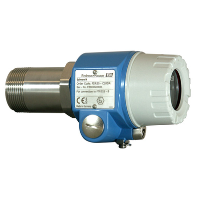
Technical Data
ComparePoint Level / Solids
| Measuring Principle | |
| Characteristic / Application | Microwave receiver |
| Ambient temperature | -20 °C ... 70 °C (-4 °F ... 158 °F) |
| Process temperature | Waves emitted from outside (non-contact): any Waves emitted within installation (contact): -20°C...70°C (-4°F...158°F) |
| Process pressure / max. overpressure limit | Waves emitted from outside (contactless): any Waves emitted within installation (contact): 0.8 bar abs ... 4,8 bar abs (12 psi ... 70 psi) |
| Min. density of medium | Solid weight: >10 g/l |
| Main wetted parts | Within installation: Aluminium, PTFE Or: non-contact |
| Process connection | 1-1/2" G + NPT With wave emission from outside / mounting from outside, metal container must not be made of metal |
| Process connection hygienic | With waves emitted from outside (non-contact) |
| Communication | Transmitter: Relays, DPDT |
| Certificates / Approvals | ATEX, IEC Ex |
| Options | Flange |
| Components | Emiter: FQR50 Transmitter: FTR325 |
| Successor | Soliwave FDR57 |
| Application limits | With waves emitted from outside (non-contact) Solid weight: <10g/l |
Product Overview
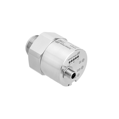
The Soliwave FDR50 microwave barrier receiver is suitable for non-contact limit detection and can be installed in vessels, ducts, shafts or free-fall shafts, or outside non-metallic vessels for measuring, controlling and counting various types of bulk solids. It can be used together with the Soliwave FQR50 transmitter.
-
Benefits
-
Flush, non-contact installation
-
Robust mechanical design: - no wear; - long service life; - maintenance-free.
-
The signal strength can be displayed on the receiver.
-
Adjustable sensitivity
-
Easy installation using an R 1-1/2 or 1-1/2 NPT thread
-
Compliant with ATEX 1/2GD and IECEx standards
-
Application
-
The Soliwave microwave limit switch is suitable for non-contact limit detection and can be installed in vessels, ducts, shafts or free-fall shafts, or outside non-metallic vessels for measuring, controlling and counting various types of bulk solids.
-
Typical bulk solids measured include:
-
Wood chips, wood dust and flour
-
Gypsum, cement and lime
-
Paper and cardboard
-
Gravel and sand
-
Common dry powders
-
Bagged or boxed packages, etc.
Spare Parts & Accessories 56
56 spare parts · click to collapse
| Order code | Description | |
|---|---|---|
| 52022365 | Electronic insert D-A1, FDR50PCB receiver. Mounted on holding plate. Non-hazardous area. Measuring range max. 8m. Usage: FDR50. | Details |
| 52022366 | Electronic insert D-A2, FDR50PCB receiver. Mounted on holding plate. Non-hazardous area. Measuring range max. 20m. Usage: FDR50. | Details |
| 52022367 | Electronic insert D-B1, FDR50PCB receiver. Mounted on holding plate. ATEX II 1/2D IP66 T102oC. Measuring range max. 8m. Usage: FDR50. | Details |
| 52022368 | ***Electronic insert D-B2, FDR50PCB receiver. Mounted on holding plate. ATEX II 1/2D IP66 T102oC. Measuring range max. 20m. Usage: FDR50. | Details |
| 71062118 | *** Electronic ModulePCB for receiver mounted in holding plate. ATEX II 1/2GD Ex ia IIC T4. Measuring range max. 8m. Usage: FDR50. | Details |
| 71062121 | *** Electronic ModulePCB for receiver mounted in holding plate. ATEX II 1/2GD Ex ia IIC T4. Measuring range max. 20m. Usage: FDR50. | Details |
| 71062123 | *** Electronic ModulePCB for receiver mounted in holding plate. IECEx 1/2GD Ex ia IIC T4. Measuring range max. 8m. Usage: FDR50. | Details |
| 71062124 | *** Electronic ModulePCB for receiver mounted in holding plate. IECEx 1/2GD Ex ia IIC T4. Measuring range max. 20m. Usage: FDR50. | Details |
| 71113441 | HT adapter R1-1/2 + Rp1-1/2, 316Ti, applicable models:Usage: FDR50, FDR56/FDR57, FQR50, FQR56/FQR57, FTR20. | Details |
| 71113449 | HT-adapter NPT1-1/2, 316Ti, suitable for model: FDR50Usage: FDR50, FDR56/FDR57, FQR50, FQR56/FQR57, FTR20. | Details |
| 71108383 | Flange DN40 PN40, Rp1-1/2, 316Ti, 3.1 EN1092EN1092-1,A. Inspection cert. EN10204-3.1 material (316Ti wetted parts). Usage: FDR50, FDR56/FDR57, FQR50, FQR56/FQR57, FTR20. | Details |
| 71006345 | Flange DN40 PN6, Rp1-1/2, Alu, hole circle: 1Hole circle: 100mm. Usage: FDR50, FDR56/FDR57, FQR50, FQR56/FQR57, FTR20. | Details |
| 71006348 | Flange DN40 PN40, Rp1-1/2, 316Ti EN1092-1, AEN1092-1, A. Usage: FDR50, FDR56/FDR57, FQR50, FQR56/FQR57, FTR20. | Details |
| 71108388 | Flange DN50 PN16, Rp1-1/2, 316Ti, 3.1 EN1092EN1092-1,A. Inspection cert. EN10204-3.1 material (316Ti wetted parts). Usage: FDR50, FDR56/FDR57, FQR50, FQR56/FQR57, FTR20. | Details |
| 71006350 | Flange DN50 PN16, Rp1-1/2, 316Ti EN1092-1, AEN1092-1, A. Usage: FDR50, FDR56/FDR57, FQR50, FQR56/FQR57, FTR20. | Details |
| 71006352 | Flange DN100 PN16, Rp1-1/2, 316Ti EN1092-1EN1092-1, A. Usage: FDR50, FDR56/FDR57, FQR50, FQR56/FQR57, FTR20. | Details |
| 71108390 | Flange DN100 PN16, Rp1-1/2, 316Ti, 3.1 EN109EN1092-1,A. Inspection cert. EN10204-3.1 material (316Ti wetted parts). Usage: FDR50, FDR56/FDR57, FQR50, FQR56/FQR57, FTR20. | Details |
| 71006346 | Flange 1-1/2" 150 lbs, NPT 1-1/2, Alu Hole cirHole circle: 98.6mm. Usage: FDR50, FDR56/FDR57, FQR50, FQR56/FQR57, FTR20. | Details |
| 71006349 | Flange 1-1/2" Cl.150, NPT1-1/2, 316Ti ASME BASME B16.5. Usage: FDR50, FDR56/FDR57, FQR50, FQR56/FQR57, FTR20. | Details |
| 71108387 | Flange 1-1/2" Cl.150, NPT 1-1/2, 316Ti, 3.1 ASMEASME B16.5. Inspection cert. EN10204-3.1 material (316Ti wetted parts). Usage: FDR50, FDR56/FDR57, FQR50, FQR56/FQR57, FTR20. | Details |
Configurator / Comparison
Source:Endress+Hauserwebsite public information
Manuals & Documents 3
All documents for this modelCase Studies
Municipal Wastewater Treatment · microwave limit — Application Case
Project Overview
The site is the inlet, biological and outlet stages of a municipal plant. The customer wanted microwave limit properly configured on the existing plant, with the aim of microwave point-level detection for solids or liquids.
Technical Challenges
What actually causes trouble is high solids and corrosive fractions, with large diurnal flow swings, and effluent parameters drift and probes foul with sludge and biofilm. All of this means the microwave limit configuration has to involve choosing contacting or non-contacting by stickiness and mounting position.
Configuration
Supply and installation were organised through the level range: level solution matched to the actual tank and silo geometry. On site this meant choosing contacting or non-contacting by stickiness and mounting position, checked line by line against: stable compliance with Grade 1A discharge limits and online data reporting.
Performance
After commissioning the outcome is build-up does not affect switching, keeping point detection dependable, and the readings are now used for process tuning.
Food & Beverage · microwave limit — Application Case
Site Conditions
This is a Food & Beverage customer whose plant is at dosing, pasteurising, filling and CIP stages. The main task was microwave point-level detection for solids or liquids.
The Problem
The difficulty lies in syrups, dairy and beverages that scale easily, under strict hygienic requirements; at the same time frequent cleaning demands instruments that withstand hot CIP/SIP caustic cycles. Specification therefore means choosing contacting or non-contacting by stickiness and mounting position.
What We Did
We took a level range approach — level solution matched to the actual tank and silo geometry. Delivery was built around choosing contacting or non-contacting by stickiness and mounting position, with point-by-point checks on: food-safety and hygienic design per 3-A / EHEDG.
Operating Outcome
In service the system performs as intended — build-up does not affect switching, keeping point detection dependable, with routine maintenance falling noticeably.
Chemical & Pharmaceutical · microwave limit — Application Case
Application Context
reactors, metering vessels and finished-product tanks is a typical Chemical & Pharmaceutical duty. The project started from microwave limit, focusing on microwave point-level detection for solids or liquids.
Process Constraints
corrosion plus Ex protection shortens instrument life and makes downtime costly, and highly corrosive media with solvents and crystallisation, partly in explosive atmospheres only amplify it. The microwave limit specification must therefore cover choosing contacting or non-contacting by stickiness and mounting position.
Delivery Approach
Delivery was handled as the level range — level solution matched to the actual tank and silo geometry. Execution centred on choosing contacting or non-contacting by stickiness and mounting position, together with Ex certification and GMP traceability of records.
Field Results
Operation shows the benefit clearly — build-up does not affect switching, keeping point detection dependable, with confidence in this measuring point improving markedly.
Power & Energy · microwave limit — Application Case
Customer Profile
The typical setting in Power & Energy is boiler feedwater, turbine condensate and FGD/DeNOx systems. The measuring point is microwave limit; the focus is microwave point-level detection for solids or liquids.
Key Difficulties
Conditions are high temperature and pressure with both steam and saline water and, on top of that, drift under high temperature and pressure, with very costly unplanned outages, which a standard configuration cannot handle for long. The design therefore starts with choosing contacting or non-contacting by stickiness and mounting position.
Implementation
The scope ran through the level range: level solution matched to the actual tank and silo geometry. Technically it hinges on choosing contacting or non-contacting by stickiness and mounting position, and on these requirements: compliance with power-industry codes and unit availability targets.
Customer Benefit
In practice this means build-up does not affect switching, keeping point detection dependable, which cut the workload on the site maintenance team.
Related Products
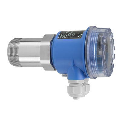 Endress+Hauser
Soliwave FDR56
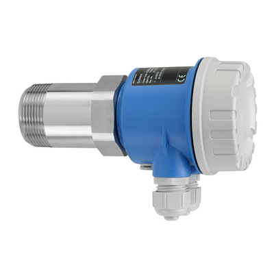 Endress+Hauser
Soliwave FQR56
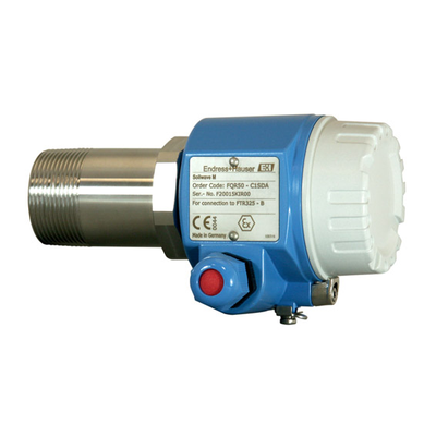 Endress+Hauser
Microwave barrier transmitter
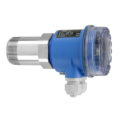 Endress+Hauser
Solimotion FTR20
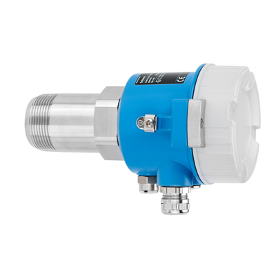 Endress+Hauser
Soliwave FQR57
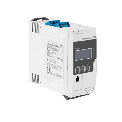 Endress+Hauser
Nivotester FTR525
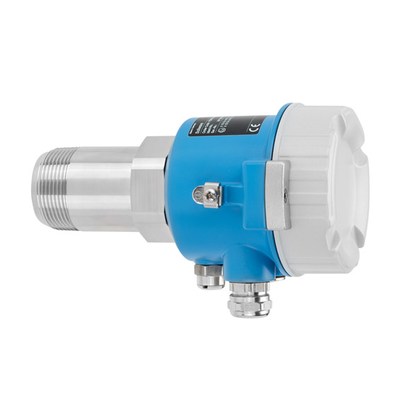 Endress+Hauser
Soliwave FDR57
 Endress+Hauser