
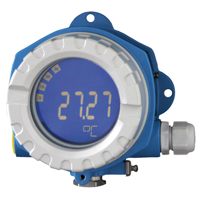
Technical Data
CompareProcess indicator & control units
| Measuring Principle | Fieldbus indicators |
| Measuring principle | 8 channel field indicator for fieldbuses |
| Function | Display values Advanced diagnostic |
| Display | High contrast backlit LCD with bargraph TAG/unit |
| Power Supply | Not defined |
| Input | Foundation Fieldbus protocol PROFIBUS PA protocol |
| Output | Not defined |
| Software functions | Listener Mode On Foundation Fieldbus also function block connection: Display transducer block Advanced diagnostic block 2 x input selector Arithmetic block Integrator block PID block |
| Certificates | ATEX Ex ia, Ex ic, Ex db, Ex tb, Ex nA CSA General Purpose CSA IS, NI, XP, DIP FM IS, NI, XP, DIP IECEx Ex ia, Ex db, Ex tb IND Ex PESO Ex |
| SIL | Not defined |
| Panel mounting | field |
RID14 field indicator, loop-powered, Ex d, 8-channel field device for FOUNDATION Fieldbus™ or PROFIBUS®
Benefits
-
Simple, standard fieldbus communication protocol
-
Up to 8 input channels or digital channels in listening mode
-
Clear backlit LC bar graph display, fault diagnostic symbols and clear text fields
-
No external power supply required
-
International approvals
Applications
The 8-channel field indicator displays measured values, calculated values and status information of fieldbus servo devices in FOUNDATION Fieldbus or PROFIBUS® PA networks. In listening mode, the device listens to the configured fieldbus address and displays the values without increasing bus traffic. In addition to FOUNDATION Fieldbus, the values available on the bus can be displayed via function block interconnection. Engineering units or TAGs are displayed in plain text, and the display also provides a bar graph so that status trends can be seen at a glance.
Spare Parts & Accessories 18
18 spare parts · click to collapse
| Order code | Description | |
|---|---|---|
| XPR0010- | Spare part RIA14, XPR0010 | Enquire |
| 71310423 | Display housing fixing kit (3 pcs) | Details |
| RIA141X- | Spare Part RIA141 RIA141X- | Enquire |
| 71502617 | O-ring 88x3 HNBR 70° Shore PTFE_5pcsPacking unit: 5 pieces | Details |
| RID14X- | RID14 spare parts RID14X | Enquire |
| RIA141G- | Housing RIA141G | Enquire |
| RID14X- | RID14 spare parts RID14X | Enquire |
| 51004948 | front cover latch pinScrew, washer, spring washer | Details |
| XPT0002- | plug connector | Enquire |
| RK01- | System component RK01 | Enquire |
| 71502941 | O-Ring 18.77x1.78 HNBR 70° Shore PTFEPacking unit: 10 pieces | Details |
| 71525622 | Blind plug M20x1.5 Ex-d + O-ring V4A | Details |
| 71525620 | Blind plug M20x1.5 Ex-d + O-ring, aluminium | Details |
| 71525621 | Blind plug G1/2 Ex-d + o-ring, Alu | Details |
| 71525623 | Blind plug G1/2 Ex-d + O-ring V4A | Details |
| 51006888 | blind cover | Details |
| 51004490 | blind cover | Details |
| XPRFID- | Spare RFID TAGConsists of: RFID TAG, fixing wire, crimp sleeve. | Enquire |
Configurator / Comparison
Source: Endress+Hauser public information from the website
Manuals & Documents 8
All documents for this modelCase Studies
Municipal Wastewater Treatment · Process Measuring and Control Instrument — Application Case
Application Context
the inlet, biological and outlet stages of a municipal plant is a typical Municipal Wastewater Treatment duty. The project started from Process Measuring and Control Instrument, focusing on measurement, control and recording for process loops.
Process Constraints
effluent parameters drift and probes foul with sludge and biofilm, and high solids and corrosive fractions, with large diurnal flow swings only amplify it. The Process Measuring and Control Instrument specification must therefore cover configured by input type, loop count and communication.
Delivery Approach
Delivery was handled as the system components range — supplying as a full cabinet and signal-chain configuration. Execution centred on configured by input type, loop count and communication, together with stable compliance with Grade 1A discharge limits and online data reporting.
Field Results
Operation shows the benefit clearly — configured on site, cutting back-and-forth during system commissioning, with confidence in this measuring point improving markedly.
Food & Beverage · Process Measuring and Control Instrument — Application Case
Customer Profile
The typical setting in Food & Beverage is dosing, pasteurising, filling and CIP stages. The measuring point is Process Measuring and Control Instrument; the focus is measurement, control and recording for process loops.
Key Difficulties
Conditions are syrups, dairy and beverages that scale easily, under strict hygienic requirements and, on top of that, frequent cleaning demands instruments that withstand hot CIP/SIP caustic cycles, which a standard configuration cannot handle for long. The design therefore starts with configured by input type, loop count and communication.
Implementation
The scope ran through the system components range: supplying as a full cabinet and signal-chain configuration. Technically it hinges on configured by input type, loop count and communication, and on these requirements: food-safety and hygienic design per 3-A / EHEDG.
Customer Benefit
In practice this means configured on site, cutting back-and-forth during system commissioning, which cut the workload on the site maintenance team.
Chemical & Pharmaceutical · Process Measuring and Control Instrument — Application Case
Project Background
The project covers reactors, metering vessels and finished-product tanks. The work centres on Process Measuring and Control Instrument and the core task is measurement, control and recording for process loops.
Operating Challenges
The medium and duty are characterised by highly corrosive media with solvents and crystallisation, partly in explosive atmospheres, and corrosion plus Ex protection shortens instrument life and makes downtime costly. So Process Measuring and Control Instrument cannot be specified generically — it calls for configured by input type, loop count and communication.
Solution
The Ainstru engineering team worked through the system components range: supplying as a full cabinet and signal-chain configuration. The configuration involves configured by input type, loop count and communication, with these requirements in view: Ex certification and GMP traceability of records.
Results
Since start-up the system has run steadily; the practical result is configured on site, cutting back-and-forth during system commissioning.
Power & Energy · Process Measuring and Control Instrument — Application Case
Project Overview
The site is boiler feedwater, turbine condensate and FGD/DeNOx systems. The customer wanted Process Measuring and Control Instrument properly configured on the existing plant, with the aim of measurement, control and recording for process loops.
Technical Challenges
What actually causes trouble is high temperature and pressure with both steam and saline water, and drift under high temperature and pressure, with very costly unplanned outages. All of this means the Process Measuring and Control Instrument configuration has to involve configured by input type, loop count and communication.
Configuration
Supply and installation were organised through the system components range: supplying as a full cabinet and signal-chain configuration. On site this meant configured by input type, loop count and communication, checked line by line against: compliance with power-industry codes and unit availability targets.
Performance
After commissioning the outcome is configured on site, cutting back-and-forth during system commissioning, and the readings are now used for process tuning.
Related Products
 Endress+Hauser
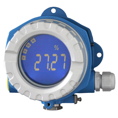
Field Indicator RIA14
 Endress+Hauser
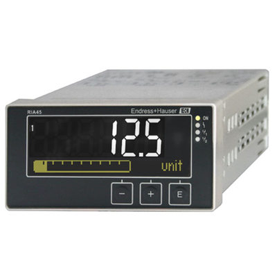
Panel Meter with Control Unit RIA45
 Endress+Hauser
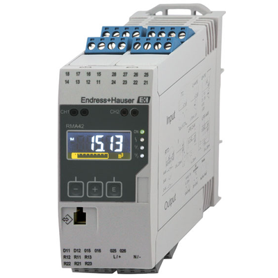
Process Transmitter + Control Unit RMA42
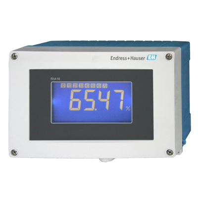 Endress+Hauser
Field Indicator RIA16
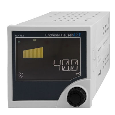 Endress+Hauser
Panel Meter RIA452
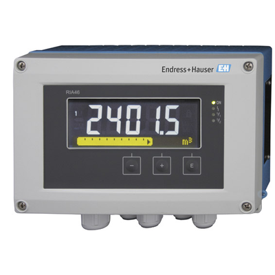 Endress+Hauser
Field Meter with Control Unit RIA46
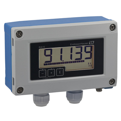 Endress+Hauser
Loop Powered Process Indicator RIA15
 Endress+Hauser